Condensing heat-exchange copper tube for an flooded type electrical refrigeration unit

a heat exchange tube and refrigeration unit technology, applied in indirect heat exchangers, refrigeration components, lighting and heating apparatus, etc., can solve the problems of reducing affecting the heat exchange efficiency of so as to achieve a relatively large heat exchange area on the heat exchange tube, the effect of improving heat exchange efficiency and enhancing heat exchange efficiency

Active Publication Date: 2007-06-14
GOLDEN DRAGON PRECISE COPPER TUBE GROUP
View PDF15 Cites 70 Cited by
  • Summary
  • Abstract
  • Description
  • Claims
  • Application Information

AI Technical Summary

Benefits of technology

[0017] The present invention is advantageous over prior art in that the condensing heat-exchange tube according to the present invention provides a larger heat transfer coefficient for the inner surface as well as the outer surface of the heat-exchange tube. Therefore, the heat transfer efficiency within the tube and outside the tube is enhanced, and the overall heat transfer efficiency is improved. The explanation is as follows. Secondary fins as well as third fins are provided on the fins arranged on the outer surface of the condensing heat-exchange tube according to the invention. Beside the fins, secondary fins and third fins further increase the heat transfer area for the heat-exchange tube. Meanwhile, secondary fins and third fins help to attenuate the condensate film such that the condensate film is substantially elim

Problems solved by technology

However, current heat-exchange tubes are all problematic in that a condensate film which functions as a thermal resistance develops when the refrigerant tries to condense, which thermal resistance adversely affects the heat transfer thus degrades the refrigeration efficiency.
However, heat resistance develops between the interface of the incorporated fins and the heat-exchange tube, which degrades the heat transfer efficiency of the heat-exchange tube.
On other hand, fins directly formed on the heat-exchange tube are usually of small height, and it is difficult to achieve a relatively large heat transfer a

Method used


Image

  • Condensing heat-exchange copper tube for an flooded type electrical refrigeration unit
  • Condensing heat-exchange copper tube for an flooded type electrical refrigeration unit
  • Condensing heat-exchange copper tube for an flooded type electrical refrigeration unit

Examples


Embodiment Construction

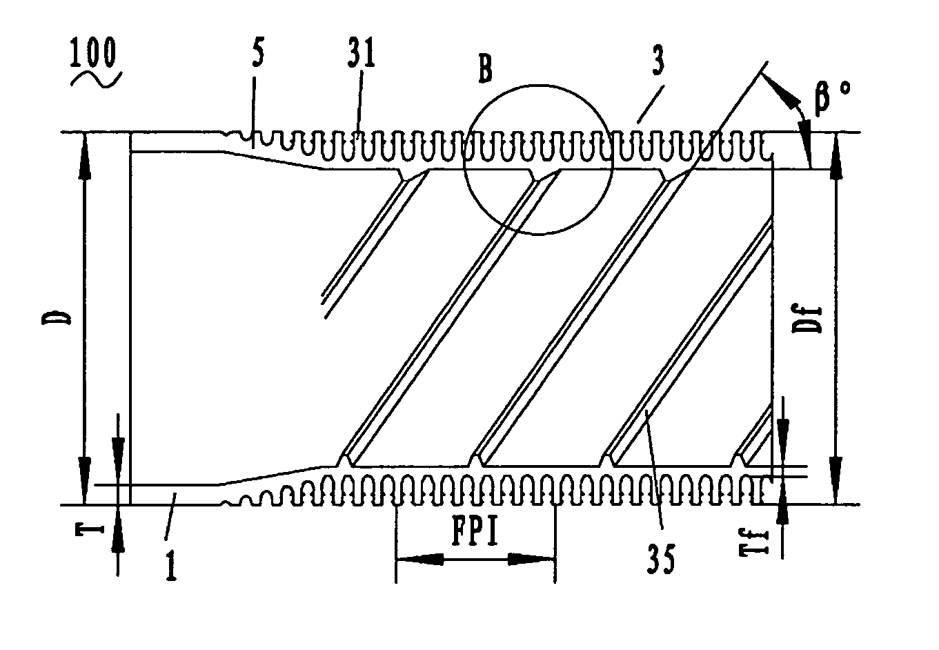
[0022] Preferred embodiments of the present invention will be described in more detail with reference to accompanying drawings. The present invention relates to a condensing heat-exchange copper tube 100 for a flooded type electrical unit, which is developed based on a research on the heat transfer mechanism for a flooded heat-exchange tube, molding device and molding process thereof, and which has a size between 12 and 26 mm, is adapted to be used in electrical cooling condenser so as to achieve a higher heat transfer efficiency.

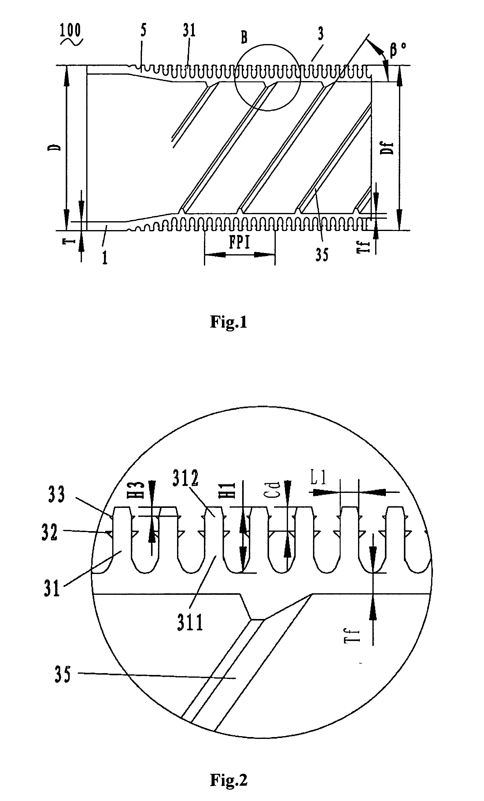
[0023] Referring to FIGS. 1 and 2, a condensing heat-exchange tube 100 according to the present invention, comprising a smooth surface portion 1, a finned portion 3 and a transitional portion connecting the smooth surface portion 1 to the finned portion 3, is manufactured by a threaded inner print and three sets of fin blades milling on the tube wall. The smooth surface portion 1 is formed by a raw tube without any processing. The diameter D of the smooth ...


PUM

PropertyMeasurementUnit
Lengthaaaaaaaaaa
Lengthaaaaaaaaaa
Lengthaaaaaaaaaa

Abstract

The present invention discloses a condensing heat-exchange copper tube for a flooded type electrical refrigeration unit, which comprises a smooth surface portion, a finned portion provided with plurality of fins and a transitional portion connecting the smooth surface portion to the finned portion. Said fin includes a fin base close to the outer surface of the heat-exchange tube and a fin top away from the outer surface. Said fin is further provided with a secondary fin at the central portion of the fin and a third fin at the top portion of the fin, wherein a certain distance is provided between two axially adjacent secondary fins or two axially adjacent third fins. Secondary fins as well as third fins according to the invention further increase the heat transfer area for the heat-exchange tube. Meanwhile, secondary fins and third fins help to attenuate the condensate film such that the condensate film is substantially eliminated, and vapor condensation and heat transfer may be carried out in a better way. At the same time, secondary fins and third fins help to guide the condensate film away from the surface of the heat-exchange tube such that heat resistance may be reduced. Thus, the overall efficiency of heat transfer through condensation is enhanced, and the property of the condenser is improved.

Description

RELATED APPLICATIONS [0001] The present application claims priority to Chinese Patent Application No. 200510134632.8, entitled “A Condensing Heat-Exchange Copper Tube for a Flooded Type Electrical Refrigeration Unit”, filed on Dec. 13, 2005. [0002] 1. Technical Field [0003] The present invention relates to a condensing heat-exchange tube, especially to a condensing heat-exchange copper tube for a flooded type electrical refrigeration unit. [0004] 2. Background [0005] In recent years, the development of the manufacturing technology for a refrigerator or an air conditioner has been advanced due to a rapid development in the refrigeration technique and air-conditioning technique. Most effort is concentrated on providing a refrigerator or air conditioner with higher efficiency, less volume and lower weight, as well as an improved refrigerant. Meanwhile, the design and technical application for a heat-exchange tube used in the refrigerator or air conditioner has also been continuously im...

Claims


Application Information

Patent Timeline
IPC IPC(8): F28F13/18F28F1/42
CPCF25B39/04F28D2021/007F28F1/26F28F1/36F28F1/40F28F13/08F28F13/187
Inventor YU, CHUANFUJIANG, QIANGYAN, JIANJUNCHANG, SHOUQING
Owner GOLDEN DRAGON PRECISE COPPER TUBE GROUP
Why Eureka
Try Eureka