Selectable focus direct part mark reader

a direct part and reader technology, applied in the field of machine vision systems and symbology readers, can solve the problems of inability to intuitively choose bright field, dark field, direct or diffuse light, and inappropriate use of highly reflective bright field illumination

Inactive Publication Date: 2007-06-14
COGNEX TECH & INVESTMENT
View PDF10 Cites 61 Cited by
  • Summary
  • Abstract
  • Description
  • Claims
  • Application Information

AI Technical Summary

Benefits of technology

[0017] In yet another embodiment of the invention, the bimodal optical subsystem uses a dichroic filter adapted to selectively reflect or transmit reflected illumination into one of two optical paths that have the same effective length, thereby enabling the formation of sharply focused images at two effective operating distances. The selective reflection by the dichroic filter is performed by providing at distinct wavelength of illum

Problems solved by technology

Conversely, where a symbology or other subject is formed on a more-irregular surface, or is created by etching or peening a pattern directly on the surface, the use of highly reflective bright field illumination may be inappropriate.
A peened/etched surface has two-dimensional properties that tend to scatter bright field illumination, thereby obscuring the acquired image.
However, it has been observed that the choice of bright field, dark field, dire

Method used


Image

  • Selectable focus direct part mark reader
  • Selectable focus direct part mark reader
  • Selectable focus direct part mark reader

Examples


Embodiment Construction

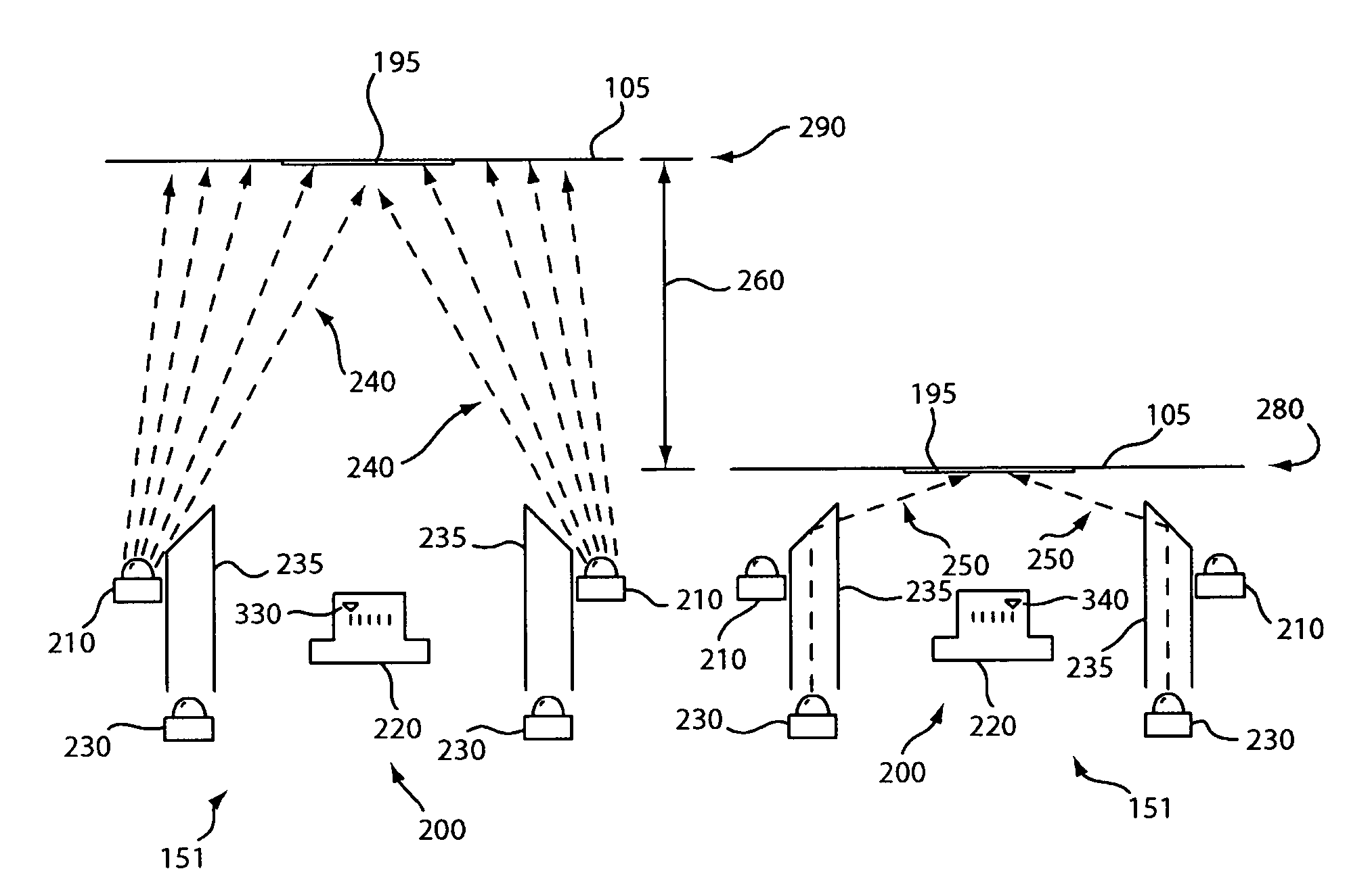
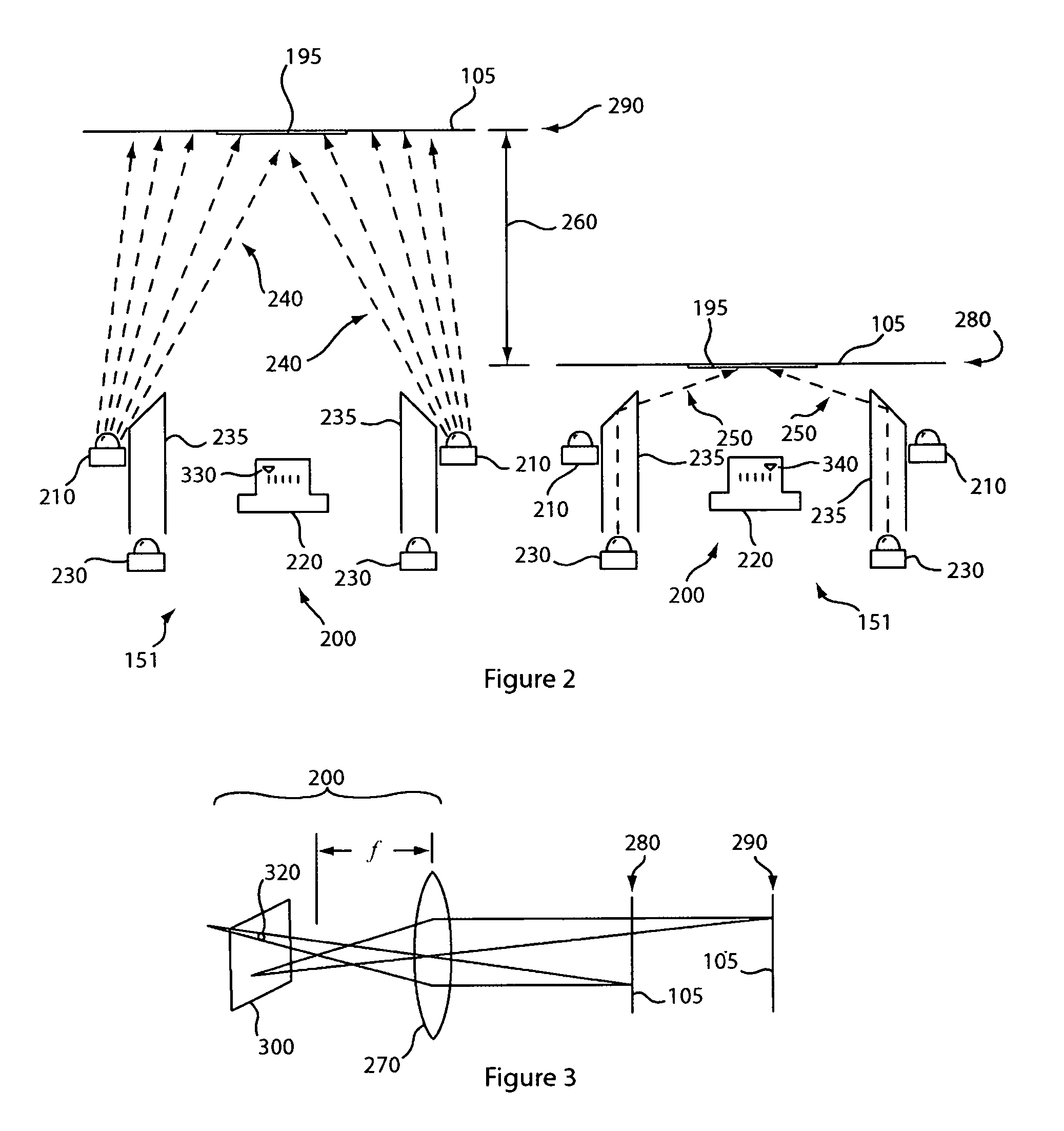
[0036]FIG. 2 depicts a cross sectional view of the image formation system 151 of a direct part mark reader according to the present invention. When configured to read a symbol 195 using bright field illumination, the bright field illuminators 210 project high-angle bright field illumination 240 at the object 105 in the bright field reading position 290. The reflected illumination captured by the imager 220 having a first focus setting 330 is passed to the on-board processor 109 (not shown) for decoding. When configured to read a symbol 195 using dark field illumination, the dark field illuminators 230 project illumination into a light pipe 235 that directs low angle dark field illumination 250 on the object 105 in the dark field reading position 280. The reflected illumination captured by the imager 220 having a second focus setting 340 is passed to the on- board processor 109 (not shown) for decoding. The relative position 260 of the object 105 is shown where the object is position...


PUM


Abstract

The present invention provides a direct part mark symbol reader that employs the use of high angle bright field illumination and low angle dark field illumination to create a digital image of the symbol that can be subsequently decoded. The reader employs an optical subsystem that produces a sharply focused image at either of the reading positions associated with the dark field illumination and the bright field illumination.

Description

BACKGROUND OF THE INVENTION [0001] 1. Field of the Invention [0002] This invention relates to machine vision systems and symbology reader that employ machine vision and more particularly to the image formation system for the same. [0003] 2. Description of the Related Art [0004] Machine vision systems use image acquisition devices that include camera sensors to deliver information on a viewed subject. The system then interprets this information according to a variety of algorithms to perform a programmed decision making and / or identification function. For an image to be most effectively acquired by a sensor in the visible, and near-visible light range, the subject should be properly illuminated. [0005] In the example of symbology reading (also commonly termed “barcode” scanning) using an image sensor, proper illumination is highly desirable. Symbology reading entails the aiming of an image acquisition sensor (CMOS camera, CCD, etc.) at a location on an object that contains a symbol (...

Claims


Application Information

Patent Timeline
IPC IPC(8): G06K7/10
CPCG06K7/10732
Inventor NUNNINK, LAURENS
Owner COGNEX TECH & INVESTMENT
Why Eureka
Try Eureka