
Digitally corrected SAR converter including a correction DAC

a digital converter and dac technology, applied in the field of digitally corrected sar converters, can solve problems such as the limitation of digitally corrected adcs

Active Publication Date: 2007-06-14
ANALOG DEVICES INC
View PDF11 Cites 38 Cited by
  • Summary
  • Abstract
  • Description
  • Claims
  • Application Information

AI Technical Summary

Benefits of technology

[0007] It is thus possible to provide a digitally corrected analog to digital converter where the steps between adjacent code transitions correspond to equally spaced changes to the input to the converter such that DNL errors are substantially removed.
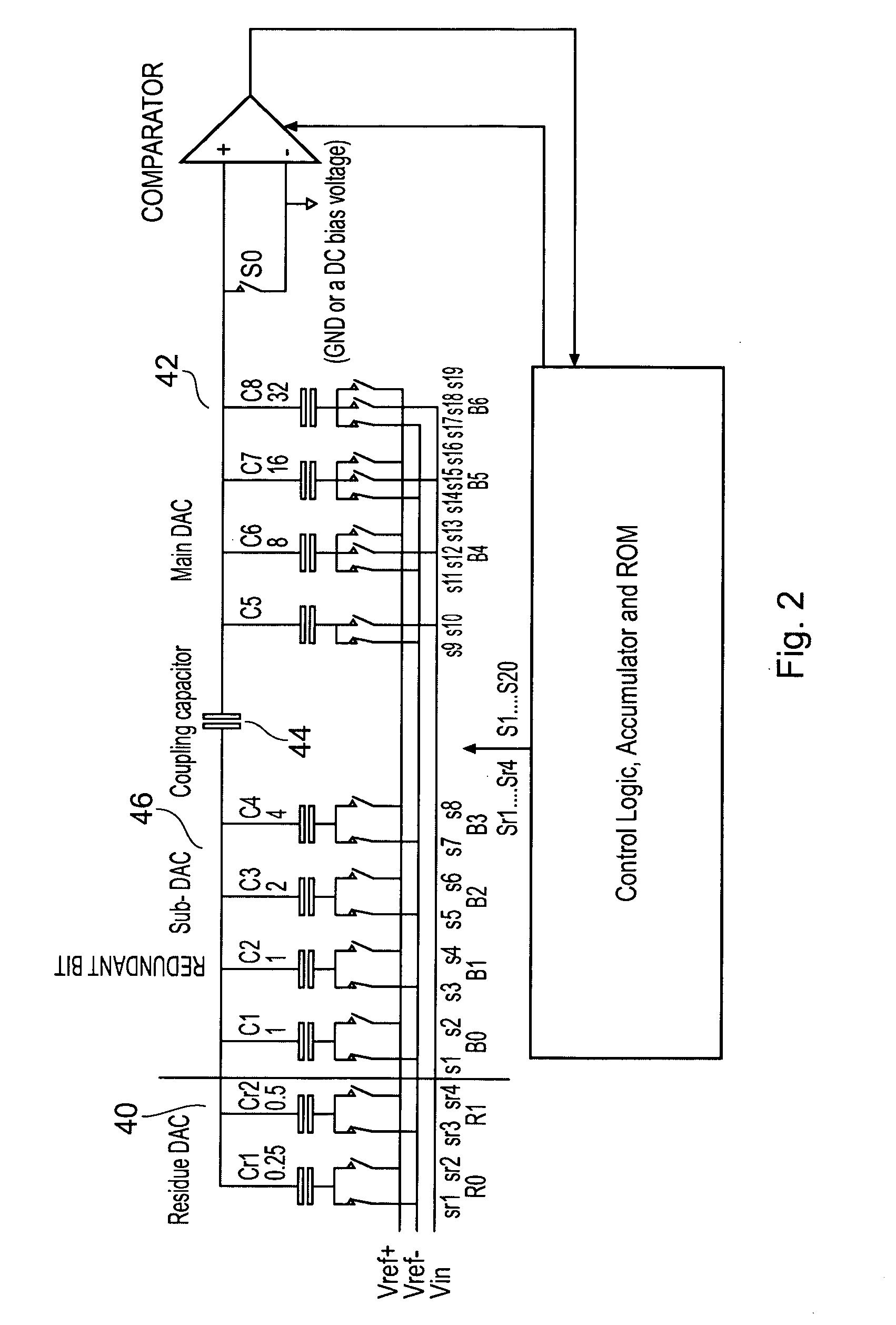
[0011] Thus the present invention provides a way of eliminating the DNL errors of a digitally corrected ADC. This is achieved by the addition of a very small DAC which in the preferred embodiment has a full scale span of just 1 LSB. This DAC accounts for the residue of the difference between the real and ideal bit weights and hence is known as the residue DAC in the description below. This invention can be considered as a hybrid between an analog and a digitally corrected ADC. The residue DAC plus any logic associated with it has an inverting operation. Hence the larger the residue fed to it the more negative will be the DAC output. Therefore the correction value or residue is, in the preferred embodiment, subtracted from the analog value output from the DAC and being tested in the successive approximation conversion process.

Problems solved by technology

This is a limitation of digitally corrected ADCs.

Method used


Image

  • Digitally corrected SAR converter including a correction DAC
  • Digitally corrected SAR converter including a correction DAC
  • Digitally corrected SAR converter including a correction DAC

Examples


Embodiment Construction

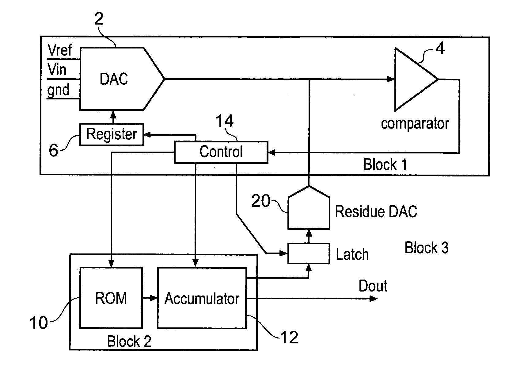
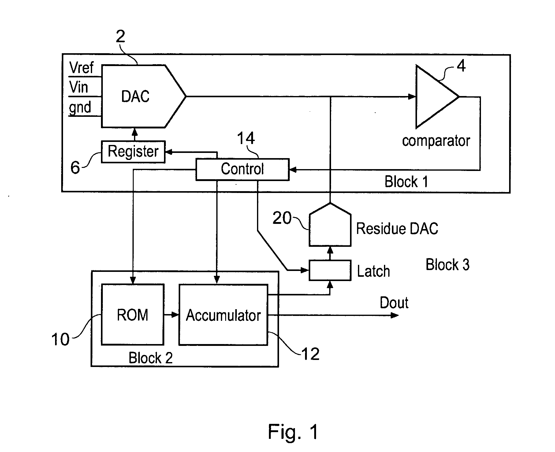
[0025]FIG. 1 shows a top level diagram of the ADC. Block 1 designates a successive conversion engine comprising a DAC 2, a comparator 4 and a successive approximation register 6, that form the major components of a SAR converter. Block 2 designates a conversion corrector which comprises a ROM 10 that contains representations of the actual (as opposed to ideal) bit weights and an accumulator 12 for adding these bit weights. Control logic 14 is shared by these blocks and is known to the person skilled in the art. A correction DAC 20 is provided to modify the voltage being compared by the comparator 4, and is responsive to an output of the accumulator 12. Block 1 and its DAC can be formed from any ADC / DAC technology and consequently needs no detailed description. It should be understood that DAC 2 is especially suited to being implemented in switched capacitor technology.

[0026] The operation of the components in block 2 should also be well understood by the person skilled in the art. ...


PUM


Abstract

An analog to digital converter having improved differential non-linearity is provided. The converter has a memory which is used to look up the actual weight or a weight error corresponding to the bits that have been kept as part of the SAR process to form an output correction value A part of this, for example a residue (the part following the decimal point in a decimal representation) is used to drive a correction DAC which causes a correction to be applied to the trial value presented to a comparator used by the ADC.

Description

FIELD OF THE INVENTION [0001] The present invention relates to an improved successive approximation routine (SAR) analog to digital converter and method of improving accuracy of an analog to digital converter. BACKGROUND OF THE INVENTION [0002] Digitally calibrated successive approximation analog to digital converters (ADC), are now well known. To avoid missing codes in such ADCs, some form of error correction is required within a digital to analog converter, DAC, provided therein. This may take the form of radix less than 2 bit weights, additional error correction bits, or other forms of redundancy. [0003] In an uncorrected traditional SAR converter, the final result is the sum of the ideal kept bit weights. For example, for a 6 bit converter which outputs the result 101011, the value of this result is taken as being 32+8+2+1=43. But suppose that for this converter we know that the actual bit weights are 32.5, 16.0, 8.4, 4.0, 2.1 and 1. A digitally corrected converter determines th...

Claims


Application Information

Patent Timeline
IPC IPC(8): H03M1/12
CPCH03M1/1047H03M1/468H03M1/68H03M1/804
Inventor HURRELL, CHRISTOPHER PETER
Owner ANALOG DEVICES INC
Learn More