Image display apparatus

a technology of image display and apparatus, applied in the direction of instruments, static indicating devices, etc., can solve the problems of unsatisfactory apparatuses when high brightness, raise size and cost problems, and apparatuses that cannot take advantage of the characteristics of input image data, or adjust optimally to ambient conditions

Inactive Publication Date: 2007-06-14
MITSUBISHI ELECTRIC CORP
View PDF5 Cites 51 Cited by
  • Summary
  • Abstract
  • Description
  • Claims
  • Application Information

AI Technical Summary

Benefits of technology

[0008] An object of the present invention is to obtain an image display apparatus capable of flexibly adjusting a balance between maximum brightness and gamut of reproducible

Problems solved by technology

In this conventional display apparatus, however, since the light emitter of each color emitter is lit for, at most, only one-third of the display time, the apparatus is unsatisfactory when high brightness is required.
It is possible to improve the brightness of the display by increasing the emission intensity of the light emitters or by increasing the number of emitters of each color, but the former strategy is limited by the opto-electrical characteristics of

Method used


Image

  • Image display apparatus
  • Image display apparatus
  • Image display apparatus

Examples


first embodiment

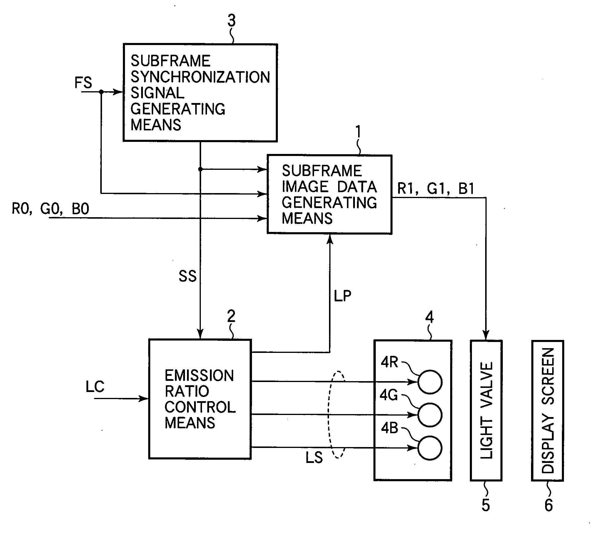
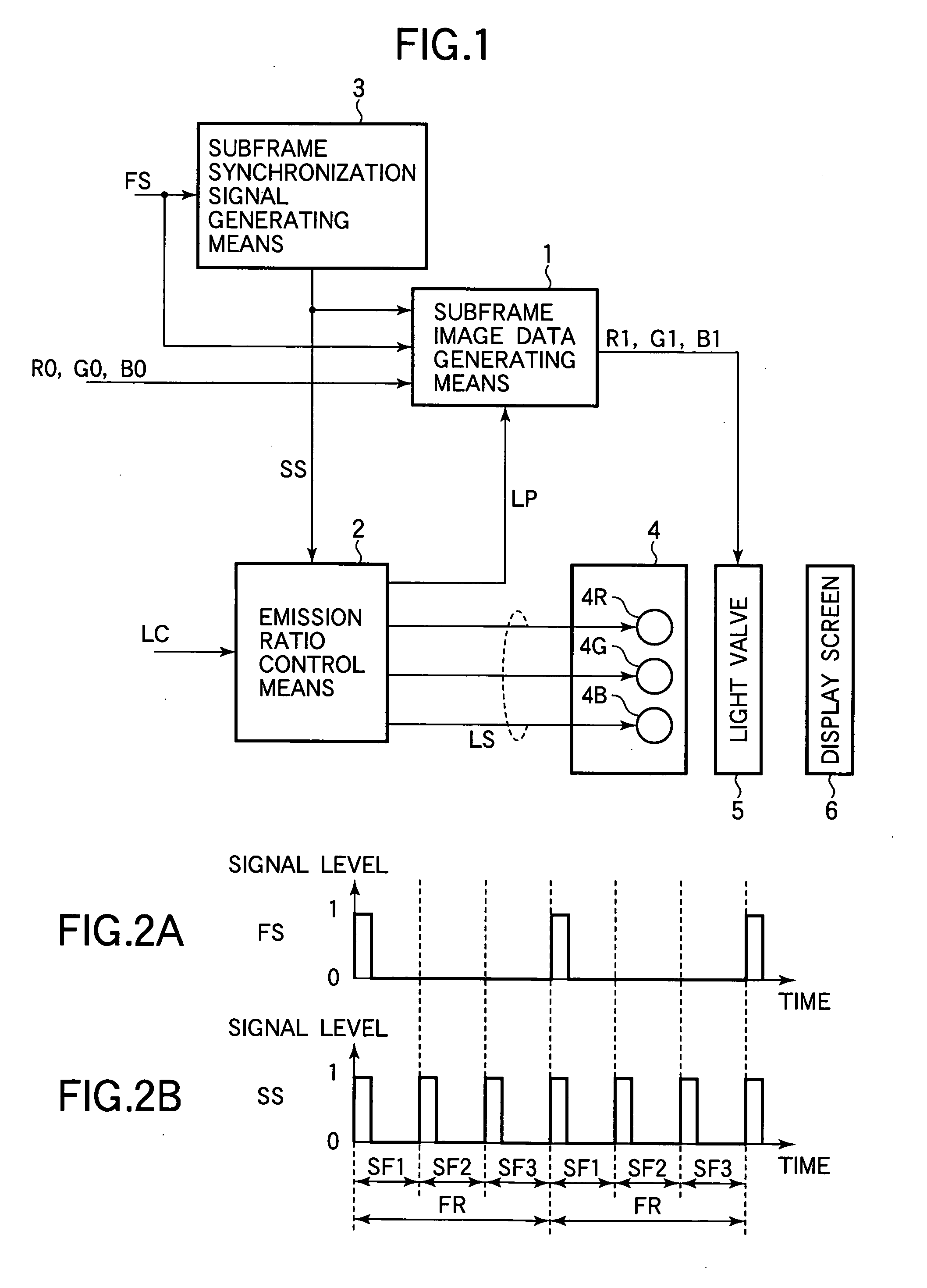
[0035] Referring to FIG. 1, the first embodiment is an image display apparatus comprising a subframe image data generating means 1, an emission ratio control means 2, a subframe synchronization signal generating means 3, a light source 4, and a light valve 5. The light source 4 comprises three light emitters 4R, 4G, 4B.

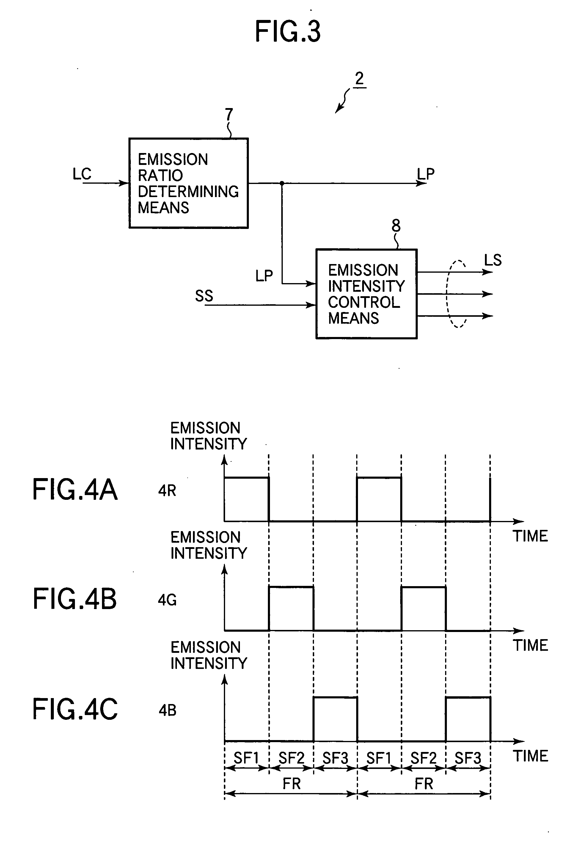
[0036] The image display apparatus receives input image data R0, G0, B0, control information LC, and a frame synchronization signal FS. The frame synchronization signal FS indicates the start of each frame of the image. The input image data R0, G0, B0 indicate the magnitudes of the red, green, and blue components of each pixel in each frame. The control information LC is derived from characteristics of the input image data or conditions under which the image display apparatus is used. The emission ratio control means 2 uses the control information LC to control the emission intensities of the light emitters 4R, 4G, 4B.

[0037] The subframe synchronization signal gener...

second embodiment

[0049] Referring to FIG. 11, the second embodiment is an image display apparatus comprising a subframe image data generating means 1, an emission ratio control means 2, a subframe synchronization signal generating means 3, a light source 4, a light valve 5, and a characterizing information detection means 16. The light source 4 comprises three light emitters 4R, 4G, 4B. The image display apparatus in the second embodiment uses characterizing information or data CH output from the characterizing information detection means 16 as the control information LC which is input to the emission ratio control means 2. The characterizing information detection means 16 generates the characterizing information CH by analyzing the input image data. The characterizing information CH indicates, for example, the distribution of pixel saturation or brightness values.

[0050] The characterizing information detection means 16 shown in FIG. 12 comprises a saturation calculation means 17, a maximum value d...

third embodiment

[0064] Referring to FIG. 20, the third embodiment is an image display apparatus comprising a subframe image data generating means 1, an emission ratio control means 2, a subframe synchronization signal generating means 3, a light source 4, a light valve 5, and a usage condition specification means 28. The light source 4 comprises three light emitters 4R, 4G, 4B. The image display apparatus of the present embodiment employs usage condition data UC output from the usage condition specification means 28 as the control information LC input to the emission ratio control means 2. The usage condition specification means 28 is used by the user to specify conditions of usage, and outputs the specified results as the usage condition data UC. The usage conditions specified by the user may include, for example, the purpose of use and the usage environment. FIG. 21 shows an exemplary graphical user interface (GUI) in the usage condition specification means 28. The interface in FIG. 21 has menu b...


PUM


Abstract

A field-sequential display apparatus having a light source that emits light of different colors in different subframes of an image controls the spectral distribution of the light emitted in each subframe according to characteristics of the input image data, or to ambient conditions or other user-specified conditions. The input image data are processed so that image colors are displayed correctly despite changes in the spectral distribution of the light-source colors. This scheme enables the gamut of reproducible colors to be altered from frame to frame to provide an appropriate balance between brightness and color saturation in each frame, and to compensate for ambient lighting conditions.

Description

BACKGROUND OF THE INVENTION [0001] 1. Field of the Invention [0002] The present invention relates to image display apparatus, more particularly to a field-sequential image display apparatus that displays color images by using a light source and a light valve. [0003] 2. Description of the Related Art [0004] An exemplary field-sequential image display apparatus using a light source and a light valve is disclosed in Japanese Patent Application Publication No. 2000-199886. The light source includes red, green, and blue light emitters, which are turned on sequentially, one at a time. The light valve is a liquid crystal panel, which is controlled according to the red, green, or blue component of the current image frame. The apparatus displays successive red, green, and blue subframes; human vision integrates the subframes and perceives a full-color image. This method of display eliminates the need to divide each picture element (pixel) on the liquid crystal panel into red, green, and blue...

Claims


Application Information

Patent Timeline
IPC IPC(8): G09G3/34
CPCG09G3/2003G09G3/34G09G3/3406G09G2310/0235G09G2320/0633G09G2360/16
Inventor KAGAWA, SHUICHISOMEYA, JUNSUGIURA, HIROAKI
Owner MITSUBISHI ELECTRIC CORP
Why Eureka
Try Eureka