

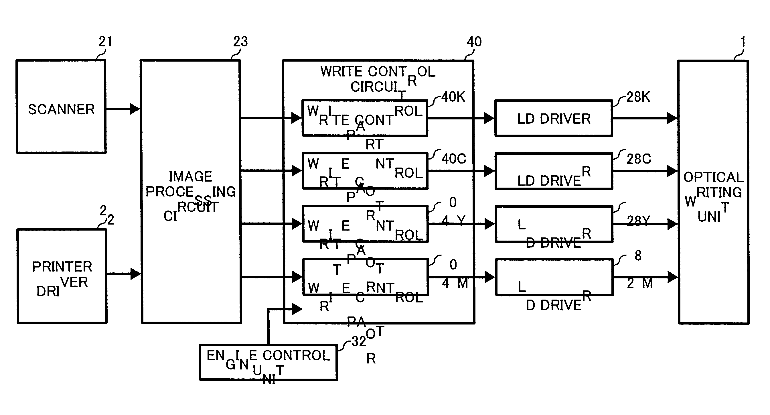
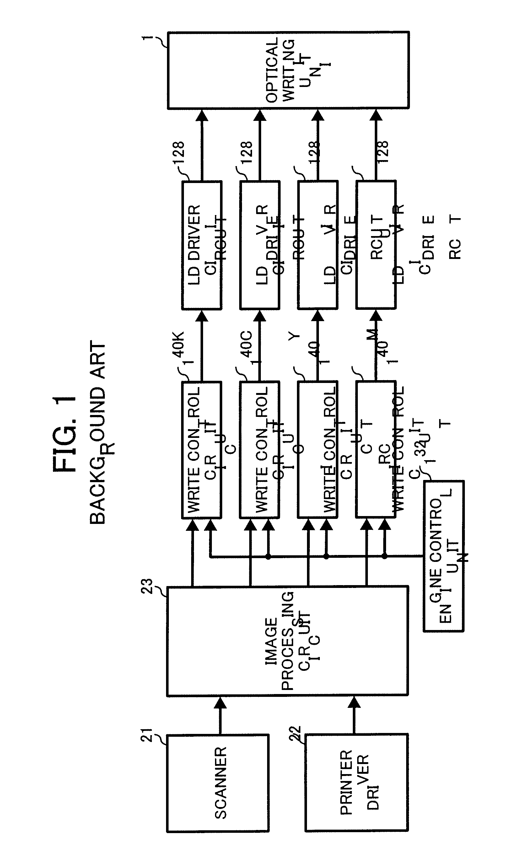
Write control circuit with optimized functional distribution
a control circuit and functional distribution technology, applied in the direction of digital output to print units, visual presentation using printers, instruments, etc., can solve the problems of huge cost and inability to provide an image forming apparatus, and achieve the effect of reducing the cost of developmen
- Summary
- Abstract
- Description
- Claims
- Application Information
AI Technical Summary
Benefits of technology
Problems solved by technology
Method used
Image

Examples
Embodiment Construction
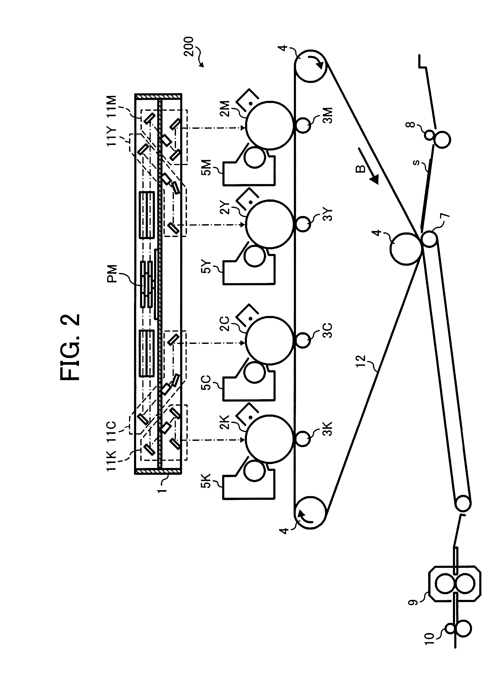
[0029] In describing preferred embodiments illustrated in the drawings, specific terminology is employed for the sake of clarity. However, the disclosure of this patent specification is not intended to be limited to the specific terminology so selected and it is to be understood that each specific element includes all technical equivalents that operate in a similar manner. Referring now to the drawings, wherein like reference numerals designate identical or corresponding parts throughout the several views, particularly to FIG. 2, a color image forming apparatus according to an exemplary embodiment of the present invention is described.
[0030] In the explanations below, the same reference numerals basically represent the same components unless otherwise noted.
[0031]FIG. 2 is a schematic illustration of an exemplary image forming mechanism of a color image forming apparatus 200 according to an exemplary embodiment of the present invention. The color image forming apparatus 200 adopts...
PUM
 Abstract
Description
Claims
Application Information