
Vehicle lighting device

a technology for lighting devices and vehicles, applied in semiconductor devices for light sources, light and heating apparatus, other domestic objects, etc., can solve the problems of increased production costs, adverse effects on light distribution, and visible burrs, and achieve good positional accuracy, short period of time, and good appearance

Inactive Publication Date: 2007-06-14
KOITO MFG CO LTD
View PDF8 Cites 49 Cited by
  • Summary
  • Abstract
  • Description
  • Claims
  • Application Information

AI Technical Summary

Benefits of technology

[0017] The invention in the present application was made in view of the problems in the related art described above and based on the knowledge of the inventor so obtained, and an object thereof is to provide an automotive lamp which includes a light source unit which enables a simple and accurate integration of a resin lens with a resin lens mounting portion, which are both light distribution control members, by means of welding, in place of the insert molding which has been used conventionally, and which is free from a defect in which burrs produced at the weld protrude towards the optical axis side of the lens.

Problems solved by technology

As a result, a mold for integrally molding both the lens 4 and the shade 6 is complex, and large-sized molding equipment becomes necessary, resulting in an increase in production cost.
However, in the event that the resin lens 4 and the resin shade 6 are integrated into the single unit by means of welding, burrs produced at the weld between the lens and the shade protrude (i.e., are exposed) towards an optical axis side of the lens 4, whereby the light distribution is adversely affected or the burrs become visible through the lens 4, such that the appearance of the headlamp when not lit is deteriorated.

Method used


Image

  • Vehicle lighting device
  • Vehicle lighting device
  • Vehicle lighting device

Examples


Embodiment Construction

[0047] Hereinafter, a mode for carrying out the invention is described based on preferred embodiments thereof.

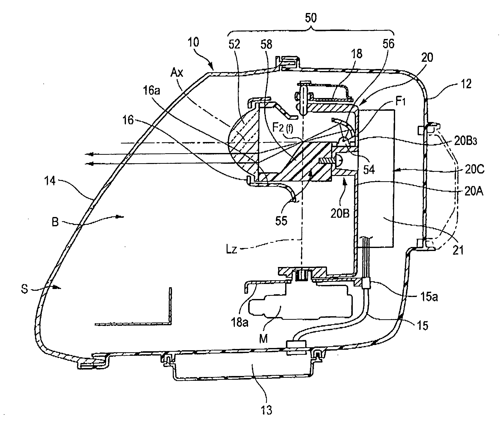
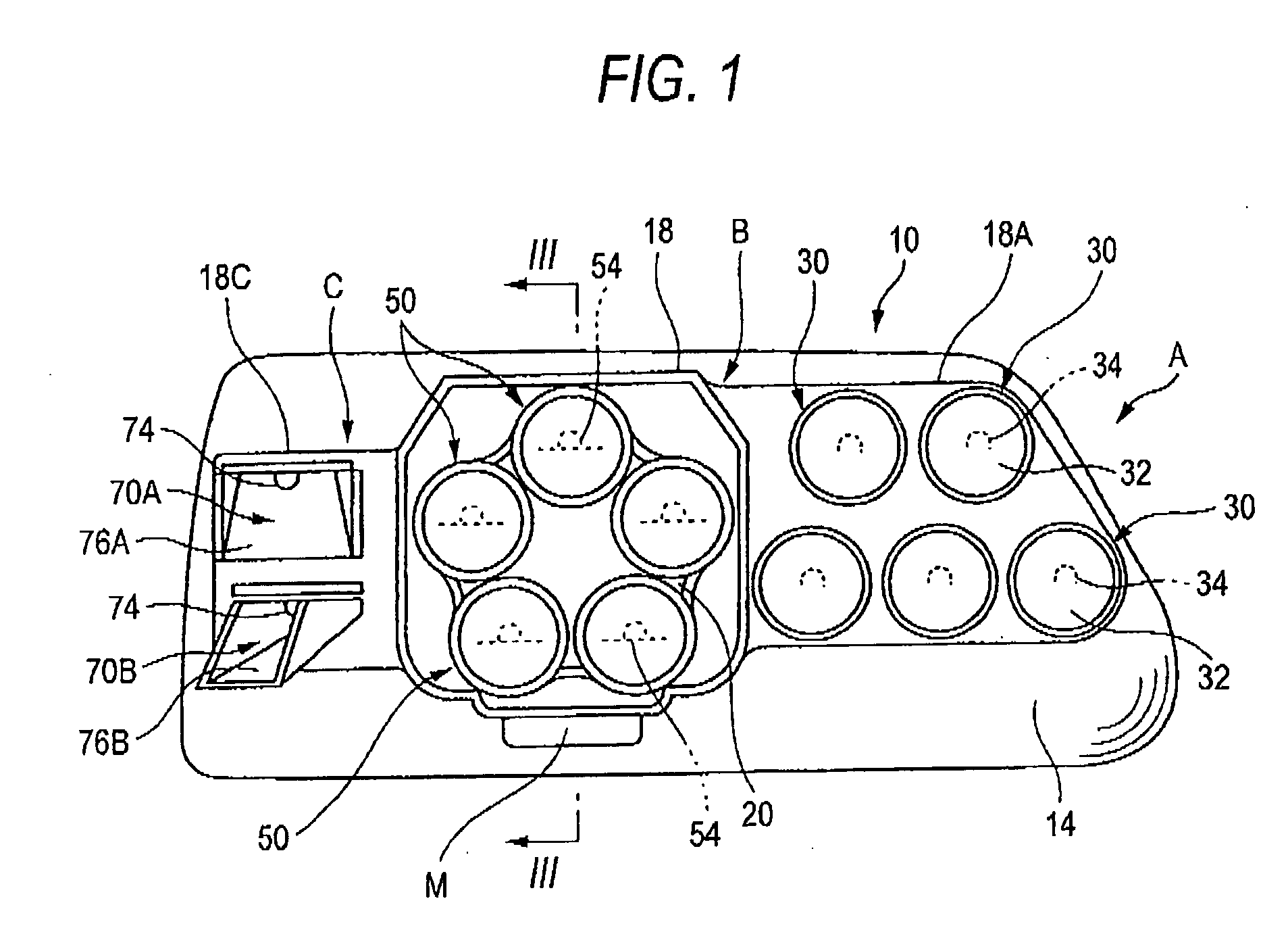
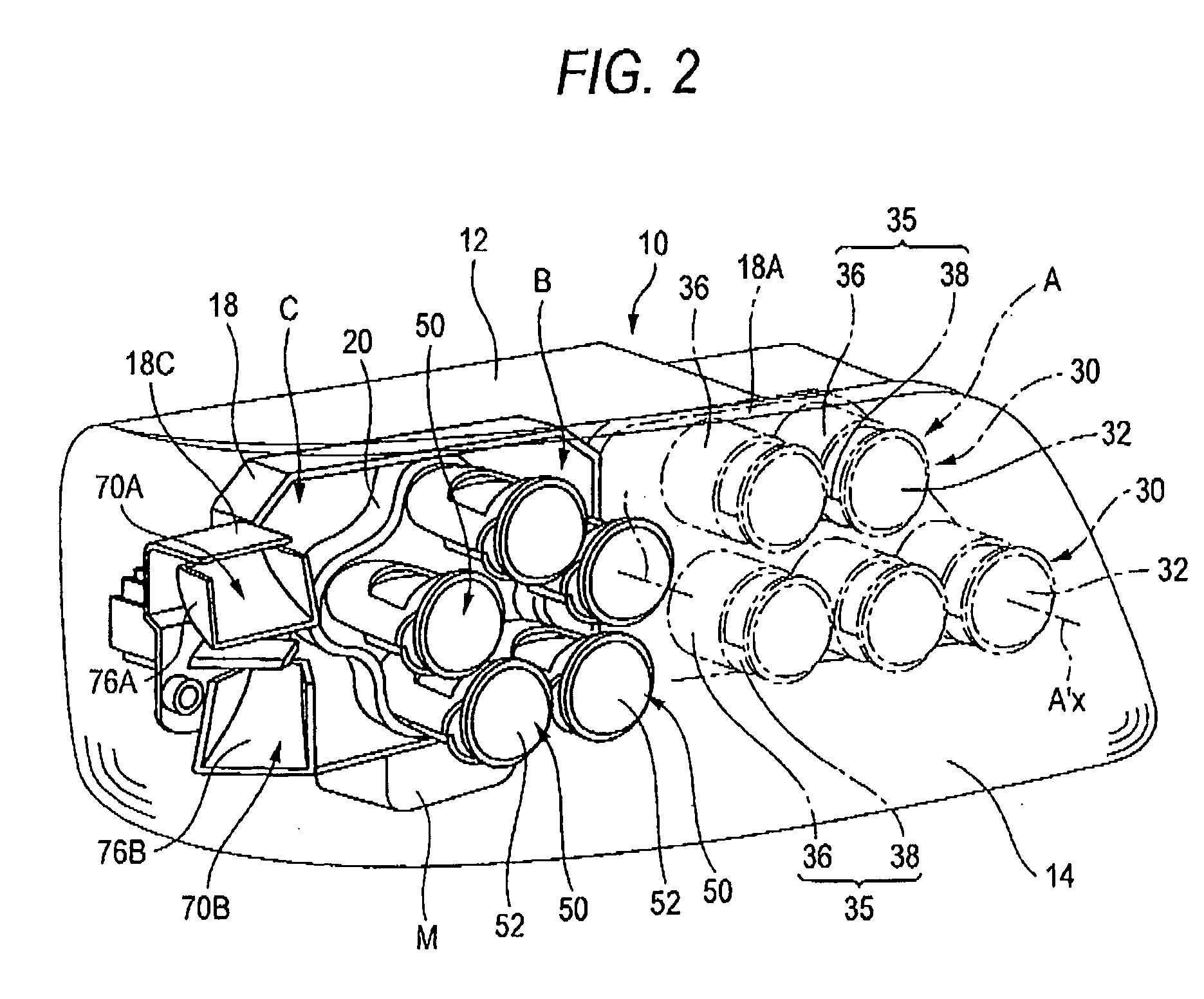
[0048] FIGS. 1 to 10 show a vehicle lighting device in accordance with a preferred embodiment of the invention.

[0049] In these figures, a vehicle lighting device 10 is a lamp that is provided on a right-hand side (as viewed from the driver's seat) of a front end portion of a vehicle and is constructed so as to accommodate a high beam lamp A, a low beam lamp B and a bending lamp C in that order as viewed from inside thereof in a lamp compartment S which is defined by a lamp body 12 and a clear transparent cover 14 mounted on a front end opening in the lamp body 12. In this preferred embodiment, the high beam lamp A is made up of five light source units in total which each use a light emitting device 34 as a light source and which are disposed in two upper and lower stages, so as to form a high beam light distribution pattern by combining respective light beam patterns of th...


PUM

PropertyMeasurementUnit
Pressureaaaaaaaaaa

Abstract

A vehicle lighting device with a lamp compartment having a light source unit disposed therein. The light source unit includes a light emitting device as a light source and a projection lens as a light distribution control member for distributing light. A face bearing portion at a distal end of a lens mounting portion of the light emitting device corresponds to a rear surface of a collar portion disposed along an outer circumference of the projection lens. Complimentary extending projections and stepped portions on the collar portion and lens mounting portion are ultrasonically welded together, and burrs formed during the welding process are prevented from protruding toward the optical axis by an erect wall of the stepped portion.

Description

CROSS-REFERENCE TO RELATED APPLICATIONS [0001] This application claims priority to Japanese Patent Application No. 2005-354580, filed Dec. 8, 2005, in the Japanese Patent Office. The priority application is incorporated by reference in its entirety. BACKGROUND OF THE INVENTION [0002] 1. Field of the Invention [0003] The present invention relates to a vehicle lighting device in which a light source unit including at least a light emitting device as a light source and a projection lens as a light distributing member for distributing light from the light source forward are provided in a lamp compartment. More particularly, the present invention relates to a vehicle lighting device that forms a predetermined light distribution pattern by combining light beam patterns omitted from a plurality of light source units provided in the lamp compartment. [0004] 2. Description of the Background Art [0005] In general, as an example, a vehicle headlamp is configured to form a low beam light distri...

Claims


Application Information

Patent Timeline
IPC IPC(8): B60Q1/00F21Y101/00
CPCB29C65/08B29C66/30223B29C66/3242B29C66/54B29L2031/7472F21S48/1159F21S48/1216F21S48/145F21S48/155F21Y2101/02B29C66/542B29C66/8322B29C65/7814B29C65/7829B29C66/12441B29C66/71B29C66/73921B29C66/81431B29L2031/30B29L2031/747F21Y2115/10F21S41/148F21S41/153F21S41/295F21S41/43F21S41/55B29K2033/08B29K2033/12B29K2069/00
Inventor WATANABE, SHIGEYUKIINABA, TETSUAKIYAMAMICHI, TATSUHIKO
Owner KOITO MFG CO LTD
Learn More