
Human target acquisition system and method

a target acquisition and target technology, applied in direction finders, direction finders using ultrasonic/sonic/infrasonic waves, instruments, etc., can solve the problems of existing systems failing to accurately map the location of objects from a distance, unable to produce an accurate, clear reading of the location of targets within the targeted structure, etc., to achieve accurate characterization and accurate determining the location

Inactive Publication Date: 2007-06-14
TAYLOR GORDON E
View PDF21 Cites 27 Cited by
  • Summary
  • Abstract
  • Description
  • Claims
  • Application Information

AI Technical Summary

Benefits of technology

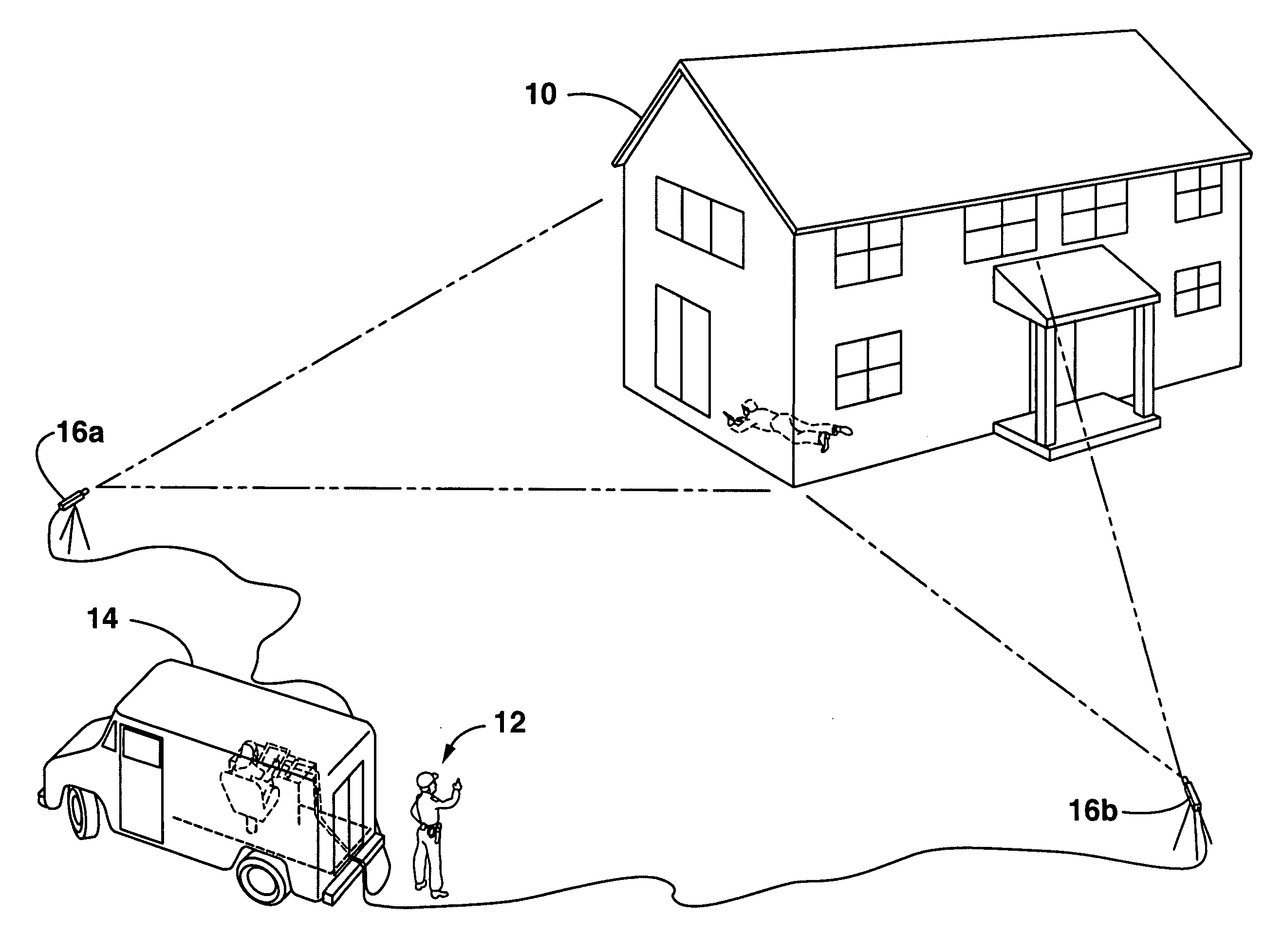
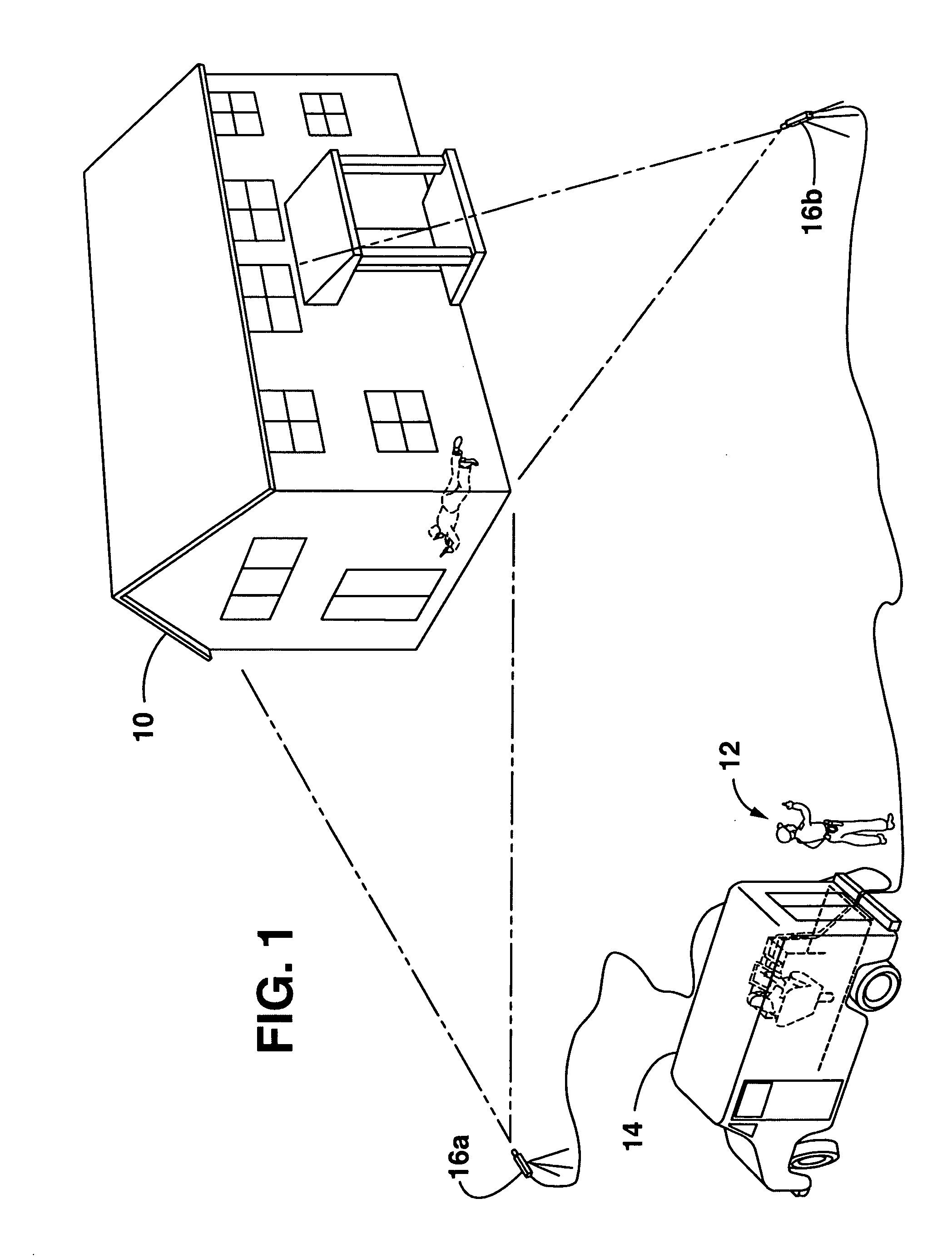
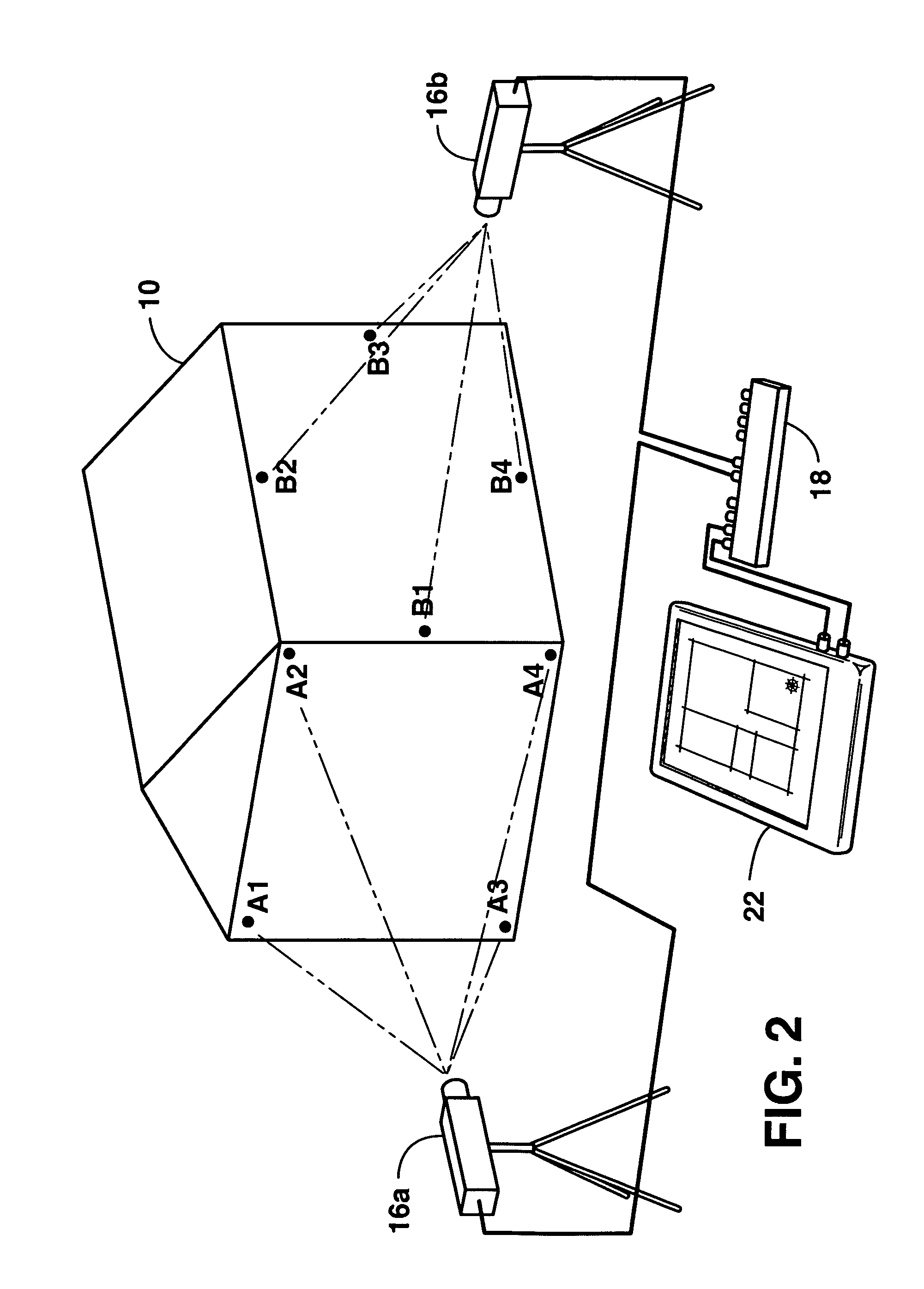
[0008] The above objectives are accomplished by providing a system for acquiring and mapping the location of a human target within a targeted zone defined by boundaries. The system includes a remote sound detection component, which may be a laser vibrometer, capable of placement at a remote safe distance without physical attachment at the targeted zone which detects sound from within the targeted zone, thereby generating a sound signal accurately representing characteristics of the detected sound. Further, a sound processing computer in communication with the sound detection component receives and analyzes the sound signal to determine the location of the sound relative to the boundaries of the targeted zone and generates a location signal representing the location of the sound. A target display is provided in communication with the sound processing computer. The display receives the location signal and outputs an accurate visual representation at the location of the target relative to the boundaries of the targeted zone. Both the sound processing computer and the target display may be embodied in a portable computer for mobile use by users at remote locations for accurately mapping the location of a human target within the targeted zone.
[0011] In a further embodiment, the invention is directed to a computer readable medium in communication with a sound detection device. A set of computer readable instructions is in communication with the computer readable medium. The set of instructions includes receiving instructions for receiving the sound signal from the sound detection device; analyzing instructions for analyzing the sound signal to determine a location of the detected sound relative to the boundaries; mapping instructions for mapping the location of the detected sound on a visual representation of the zone are included in the zone boundaries, and display instructions for visually displaying the exact location of the human target in the zone with respect to the boundaries on an associated visual display. Thus, the location of the human target may be accurately determined within the targeted zone for further action by law enforcement personnel. The analyzing instructions further include instructions for determining the loudness, time of arrival, shape and reverberation characteristics of the sound signal for accurately determining the location of the sound signal. The set of computer readable instructions further comprise noise canceling instructions for canceling any background noise before mapping the location of a signal. The set of canceling instructions include instructions for determining the origin of the sound signal received and canceling any signal not received from the desired origin before analyzing the signal. The computer readable medium may be embodied in a pen-enabled portable computer for mobile use by law enforcement at remote locations for accurately mapping the location of a human target within a targeted zone. The input received from a user via the pen-enabled portable computer, can represent external interior boundaries of the targeted zone defining the interior layout of the targeted zone.
[0012] In a further embodiment, the method for acquiring the location of a target within a targeted zone is provided. The method comprises the steps of providing a sound detection device in communication with a computer readable medium at a distance from the targeted zone, wherein input is received into the computer readable medium representing a targeted zone including the exterior boundaries of the targeted zone, A signal is received which represents the characteristics of a detected sound from the sound detection device by the computer readable medium, analyzes the signal by the computer readable medium to accurately determine the location of the detected sound based on the characteristics of the sound signal and maps the determined location of the sound relative to the exterior boundaries of the targeted zone. The location of the sound is displayed on an associated visual display depicting the graphical representation of the targeted zone.

Problems solved by technology

However, the existing systems fail to accurately map the location of the object from a distance.
The existing systems fail in one of two major ways: 1) they require the placement of sound detection devices in close proximity to the target; and, 2) they do not produce an accurate, clear reading of the location of the target within the targeted structure.
While these can produce a location of a target inside the targeted structure they are insufficient for use by law enforcement officials to locate a human target in hostage situations or standoff situations.
The necessity of having these sound detection devices close to the building structure requires the law enforcement official to place their life in jeopardy in attempting to place the sound detection device in close proximity to the structure.
The second manner in which the prior systems fail for the purposes of law enforcement are that they do not produce an accurate mapping of the location of the sound signal.
While radar, sonar and other forms of sound detection including ultrasound can be used to determine a general location, they are unable to specifically locate a target within a targeted structure.
Laser vibrometers have not been used to determine the location of human targets in targeted zones, and no computer system for processing information from a laser vibrometer and mapping location of a human target within a targeted zone has been produced.

Method used


Image

  • Human target acquisition system and method
  • Human target acquisition system and method
  • Human target acquisition system and method

Examples


Embodiment Construction

[0020] The detailed description that follows may be presented in terms of program procedures executed on a computer or network of computers. These procedural descriptions are representations used by those skilled in the art to most effectively convey the substance of their work to others skilled in the art. These procedures herein described are generally a self-consistent sequence of steps leading to a desired result. These steps require physical manipulations of physical quantities such as electrical or magnetic signals capable of being stored, transferred, combined, compared, or otherwise manipulated by a set of computer readable instructions embodied in a computer readable medium that is designed to perform a specific task or tasks. Actual computer or executable code or computer readable code may be contained within one file or one storage medium but may also span several computers or storage mediums.

[0021] The present invention is described below with reference to flowchart ill...


PUM


Abstract

The invention is a system for acquiring and mapping the location of a human target within a targeted zone defined by boundaries. The system includes a remote sound detection component, which may be a laser vibrometer, capable of placement at a remote safe distance without physical attachment at the targeted zone which detects sound from within the targeted zone, thereby generating a sound signal accurately representing characteristics of the detected sound. Further, a sound processing computer receives and analyzes the sound signal to determine the location of the sound relative to the targeted zone and generates a location signal representing the location of the sound. A target display is provided for receiving the location signal and outputting an accurate visual representation at the location of the target relative to the boundaries of the targeted zone.

Description

FIELD OF THE INVENTION [0001] This invention is directed to a system and method for acquiring the location of a target and mapping the location of the target, specifically for use by law enforcement officials in hostage or stand-off situations where the need for acquiring the location of a human target at a distance is present. BACKGROUND OF THE INVENTION [0002] The use of sound waves to determine existence of an object behind a barrier has been prevalent for a number of years. These systems are capable of determining the existence of an object, and determining the general location of the object. However, the existing systems fail to accurately map the location of the object from a distance. The existing systems fail in one of two major ways: 1) they require the placement of sound detection devices in close proximity to the target; and, 2) they do not produce an accurate, clear reading of the location of the target within the targeted structure. [0003] There are several systems incl...

Claims


Application Information

Patent Timeline
IPC IPC(8): H04B1/06
CPCG01H9/00G01S5/18G08B13/1672
Inventor TAYLOR, GORDON E.
Owner TAYLOR GORDON E
Learn More