Vertical handoff method and system in WLAN/3g integrated networks

a technology of integrated networks and vertical handoff, which is applied in the direction of electrical equipment, wireless commuication services, connection management, etc., can solve the problems of gateway taking some time to rebuild the connection to the ue, unavoidable integration between the wlan system and the 3g system, and packet loss, etc., to reduce handoff latency and packet loss

Inactive Publication Date: 2007-06-14
IND TECH RES INST
View PDF13 Cites 73 Cited by
  • Summary
  • Abstract
  • Description
  • Claims
  • Application Information

AI Technical Summary

Benefits of technology

[0009] One of the aspects of the invention is to provide a vertical handoff method and system in WALN / 3G integrated networks for reducing handoff latency.
[0011] To achieve the above and other aspects, the invention provides a vertical handoff method and system between a WLAN network and a 3G network for reducing handoff latency. A first tunnel (IPSec tunnel) is established between a relay node (TTG) and a user equipment (UE) in the WLAN network by assigning parameters SPI and TS when the user equipment is located in the WLAN network. The relay node translates the parameters TS and SPI into TFT(PF I, PF II) respectively and randomly assigns a first table index (NSAPI). Note that PF I and PF II are in packet filter type I and II, respectively. A second tunnel (GTP tunnel) between the relay node and a support node (GGSN) is established based on the TFT(PF I, PF II) and the first table index. A first table (PDP Context) is established based on the TFT(PF I, PF II) and the first table index by the GGSN, for the user equipment in the WLAN network to access 3G services. The UE randomly assigns a second table index when the user equipment roams from the WLAN network into the 3G network. Because the UE applies the same translation rules as the relay node, a third tunnel between another support node (SGSN) and the UE in the 3G network is established based on the TFT(PF I, PF II) and the second table index. A fourth tunnel between the SGSN and the GGSN is established based on the TFT(PF I, PF II) and the second table index. The GGSN searches for the first table with the first table index based on the parameter SPI in PF II of the TFT. If the search is successful, the GGSN reuses the first table by replacing the first table index by the second table index, for the user equipment in the 3G network to continue the 3G services. If the search for the first table is failed, the GGSN establishes a second table based on the TFT(PF I, PF II) and the second table index, for the user equipment in the 3G network to access 3G services.
[0012] To achieve the above and other aspects, the invention provides another vertical handoff method and system between a 3G network and a WLAN network for reducing handoff latency. A first tunnel between a support node (SGSN) and a user equipment (UE) in the 3G network is established by assigning a first table index (NSAPI) and generating a TFT(PF I) by the user equipment when the user equipment is located in the 3G network. A second tunnel between the SGSN and another support node (GGSN) is established based on the TFT(PF I) and the first table index. The GGSN establishes a first table based on the TFT(PF I) and the first table index, for the user equipment in the 3G network to access 3G services via the GGSN. The UE translates the TFT(PF I) into a parameter TS and assigns another parameter SPI when the UE roams from the 3G network into the WLAN network. A third tunnel between a relay node (TTG) and the user equipment in the WLAN network is established based on the parameters TS and SPI. The TTG translates the parameters TS and SPI into TFT(PF I, PF II) and randomly assigns a second table index. A fourth tunnel between the TTG and the GGSN is established based on the TFT(PF I, PF II) and the second table index. The GGSN searches for the first table with the first table index based on the TFT(PFI). If the search is successful, the GGSN reuses the first table by replacing the first table index by the second table index and updating the TFT(PF I) with the TFT(PF I, PF II), for the user equipment in the WLAN network to continue the same 3G services via the GGSN. If the search for the first table is failed, the GGSN establishes a second table based on the TFT(PFI, PF II) and the second table index, for the user equipment in the WLAN network to access 3G data services via the GGSN.

Problems solved by technology

The integration between the WLAN system and the 3G system is unavoidable.
However, during the UE roams into 3G network, a gateway takes some time in rebuilding connection to the UE.
If the rebuilding process takes long time, handoff latency and packet loss may occur and the 3G data services provided to the UE may be interrupted.

Method used


Image

  • Vertical handoff method and system in WLAN/3g integrated networks
  • Vertical handoff method and system in WLAN/3g integrated networks
  • Vertical handoff method and system in WLAN/3g integrated networks

Examples


first embodiment

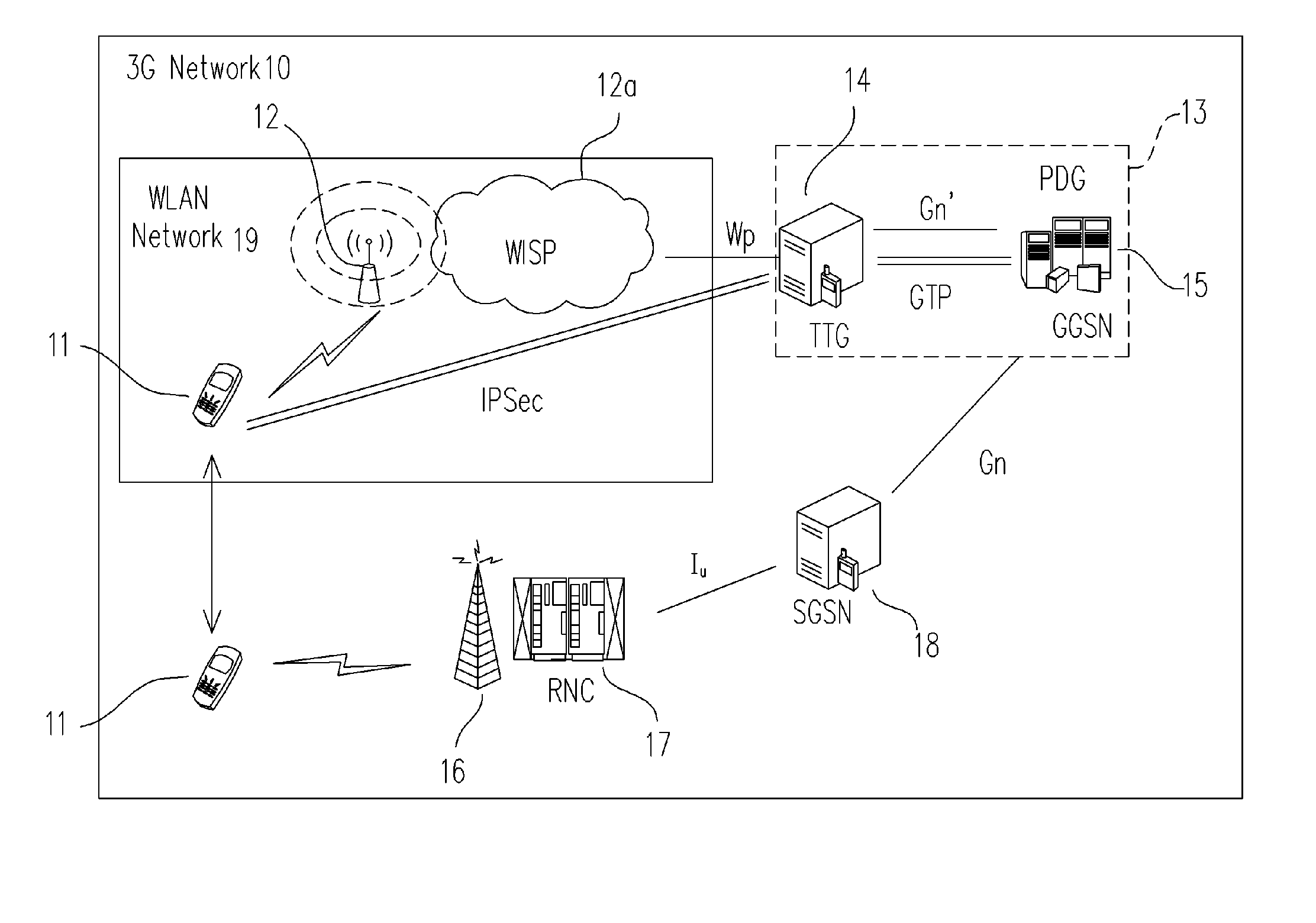
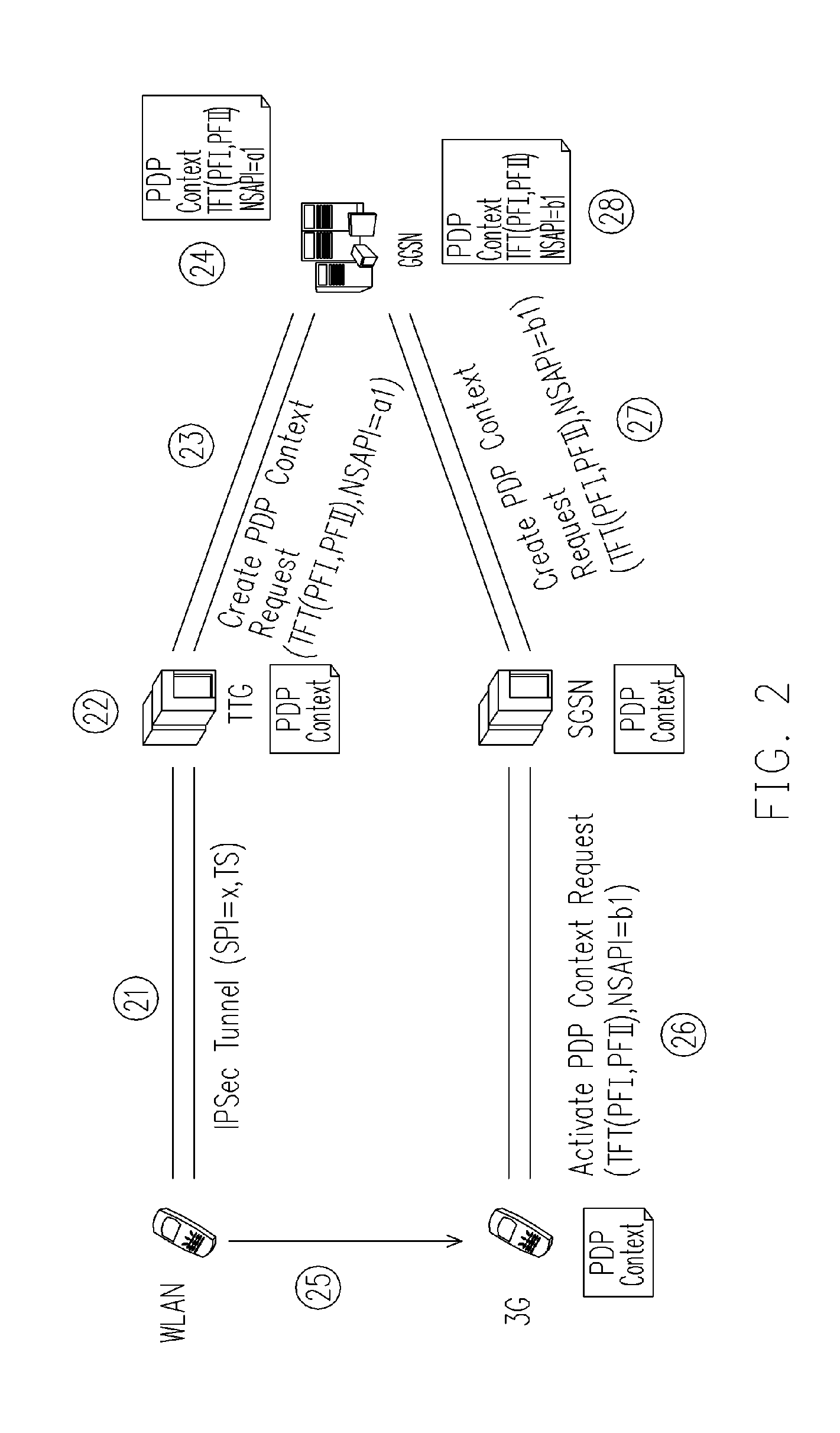
[0024]FIG. 2 shows the vertical handoff from the WLAN network to the 3G network according to the invention. When the UE wants to access 3G data services, UE has to establish connections to the GGSN (or the PDG). As shown in FIG. 2, to establish the connections, the UE first establish IPSec tunnels toward the TTG by assigning parameters SPI (security private index)=x and TS (traffic selection), as shown in Step 21. The parameter TS includes for example, a TS type field, an IP protocol ID (identification) field, a selector length field, a start port field, an end port field, a staring address field and an ending address field.

[0025] For establishing the GTP tunnels to the GGSN, the TTG has to generate or translate the parameters SPI and TS into TFT (traffic flow template) parameters. The TFT parameter may include more than one packet filters. The TTG should translate the parameter TS in the IPSec tunnel into a packet filter type I (PF I) or TFT(PF I). The translation is straightforwar...

second embodiment

[0030]FIG. 3 shows the vertical handoff from the 3G network to the WLAN network according to the invention. In FIG. 3, the UE accesses 3G data services when UE is located in the 3G network. Then the UE roams from the 3G network into the WLAN network and the UE still wants to continue the same 3G data services.

[0031] If the UE wants to access 3G data services when the UE is located in the 3G network, the UE needs to establish connections toward the GGSN. The UE assigns a new parameter NSAPI (a2) and generates the TFT (PF I) by itself. The UE sends an “Activate PDP Context Request” message with the newly assigned parameter NSAPI (a2) and the TFT (PF I) towards to the SGSN, as shown in Step 31. The SGSN forwards a “Create PDP Context Request” message towards to the GGSN, as shown in Step 32. This “Create PDP Context Request” message includes the TFT (PF I) and the parameter NSAPI (a2). Hence it might be that only one packet filter PFI is built for the TFT in the “Create PDP Context Req...


PUM


Abstract

An IPSec tunnel is established by assigning parameters TS and SPI being translated into TFT (PF I, PF II). A first index is assigned. A GTP tunnel is established based on TFT (PF I, PF II) and the first index. GGSN generates a table based on TFT (PF I, PF II) and the first index, for UE in WLAN network to access 3G services. UE assigns a second index when roaming into the 3G network. A tunnel between SGSN and UE is established based on TFT (PF I, PF II) and the second index. Another tunnel between the SGSN and the GGSN is established based on TFT (PF I, PF II) and the second index. GGSN searches for the table with the first index based on SPI in the TFT (PF II), for reusing the table for not interrupting 3G services provided to the UE in the 3G network.

Description

CROSS-REFERENCE TO RELATED APPLICATION [0001] This application claims the priority benefits of U.S. provisional application Ser. No. 60 / 741,950, filed on Dec. 1, 2005. All disclosure of this application is incorporated herein by reference.BACKGROUND OF THE INVENTION [0002] 1. Field of Invention [0003] The present invention relates to a vertical handoff method and system in WALN / 3G integrated networks for reducing handoff latency and data loss during vertical handoff. [0004] 2. Description of Related Art [0005] Although 3G (third generation) network can cover almost everywhere and a bunch of services are provided at cheaper price. However, a lower-cost and higher bandwidth WLAN (Wireless Local Area Network) network is a still better alternative. 3G network has a wide coverage range but a low transmission speed. On the contrary, WLAN network has a narrow coverage range but a high transmission speed. WLAN and 3G networks are complementary to each other. [0006] Owing to more convenient ...

Claims


Application Information

Patent Timeline
Patent Type & Authority Applications(United States)
IPC IPC(8): H04Q7/00H04Q7/24H04W36/14H04W76/04H04W92/02
CPCH04W36/0033H04W76/041H04W92/02H04W76/22
Inventor HSU, YU- CHINGTSAI, PAI-FENGWU, CHAO-CHING
Owner IND TECH RES INST
Why Eureka
Try Eureka