Mid-infrared raman fiber laser system

Inactive Publication Date: 2007-06-14
ELECTRONICS & TELECOMM RES INST
View PDF8 Cites 19 Cited by
  • Summary
  • Abstract
  • Description
  • Claims
  • Application Information

AI Technical Summary

Benefits of technology

[0013] The present invention provides a mid-infrared Raman optical fiber laser system that oscillates in a 3.0 to 4.0 μm range using a

Problems solved by technology

However, a silica optical fiber having phonon energy of about 1100 cm−1 cannot obtain energy shift into a mid-infrared wavelength region even if it contains a rare-earth element.
A non-oxide optical fiber having phonon energy of less than about 600 cm−1 and which is doped with a rare-earth element may obtain energy shift into the mid-i

Method used


Image

  • Mid-infrared raman fiber laser system
  • Mid-infrared raman fiber laser system
  • Mid-infrared raman fiber laser system

Examples


Embodiment Construction

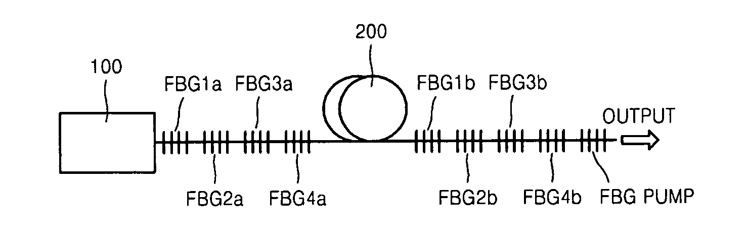
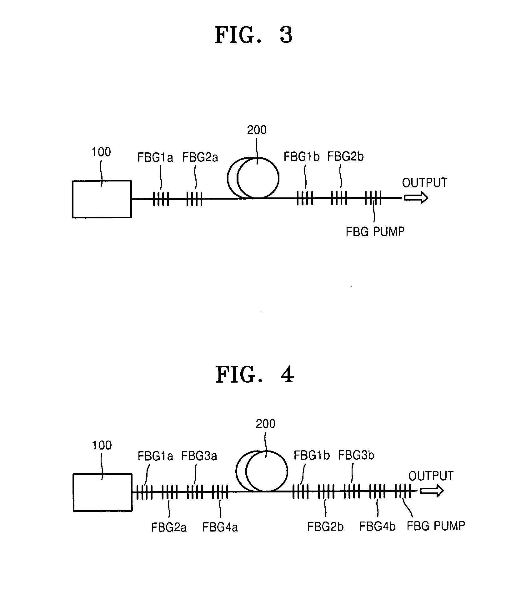
[0024] The present invention will now be described more fully with reference to the accompanying drawings, in which exemplary embodiments of the invention are shown. The invention may, however, be embodied in many different forms and should not be construed as being limited to the embodiments set forth herein; rather, these embodiments are provided so that this disclosure will be thorough and complete, and will fully convey the concept of the invention to those skilled in the art. In the drawings, the thicknesses of layers and regions are exaggerated for clarity. Like reference numerals in the drawings denote like elements, and thus their description will be omitted.

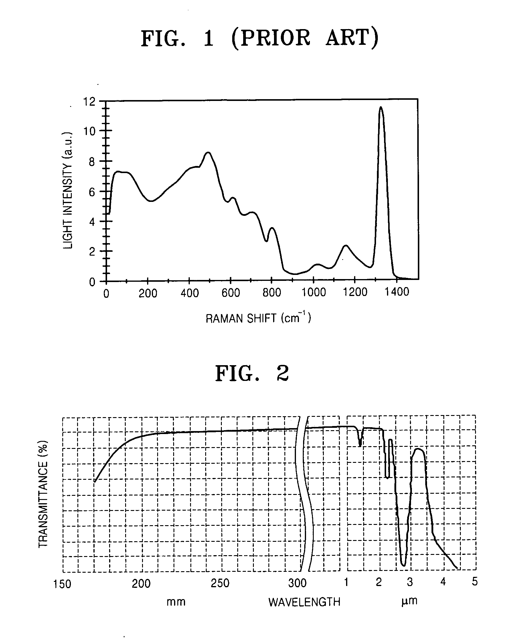
[0025] An embodiment of the present invention provides a mid-infrared optical fiber laser system using mid-infrared wavelength transmission band of a silica optical fiber and stimulated Raman scattering (SRS) characteristics of a P2O5 silica optical fiber. The silica optical fiber have already been used in optical fiber...


PUM


Abstract

Provided is a mid-infrared Raman optical fiber laser system that oscillates in a 3.0 to 4.0 μm range using a high power laser in a near-infrared wavelength region and a silica optical fiber as a pump light source and a gain medium, respectively. The system includes a plurality of pairs of FBGs (Fiber Bragg Gratings) that are disposed at either end of an optical fiber inducing Raman scattering and obtains a lasing wavelength using a plurality of stokes shifts generated by energy decrease of about 1330 cm−1 during the Raman scattering; and a pump light source that is disposed at one end of FBG pair and induces the Raman scattering in the optical fiber.

Description

CROSS-REFERENCE TO RELATED PATENT APPLICATION [0001] This application claims the benefit of Korean Patent Application No. 10-2005-0121976, filed on Dec. 12, 2005, in the Korean Intellectual Property Office, the disclosure of which is incorporated herein in its entirety by reference. BACKGROUND OF THE INVENTION [0002] 1. Field of the Invention [0003] The present invention relates to an optical fiber laser, and more particularly, to a Raman optical fiber laser with a mid-infrared lasing wavelength that uses a silica optical fiber as a gain medium. [0004] 2. Description of the Related Art [0005] Optical fiber lasers guide pump light emitted from a pump light source or laser light into an optical fiber. An optical fiber laser provides high efficiency of conversion of pump light and enables a simple cavity design by eliminating alignment in optical components. It also has excellent mode characteristics due to stable cavity alignment and power output and is easy to use because an output o...

Claims


Application Information

Patent Timeline
IPC IPC(8): H01S3/30
CPCH01S3/0675H01S3/08086H01S3/1691H01S3/302H01S3/067H01S3/10
Inventor AHN, JOON TAESEO, HONG SEOKCHUNG, WOON JINPARK, BONG JE
Owner ELECTRONICS & TELECOMM RES INST
Why Eureka
Try Eureka