Organism information detection device and sphygmomanometer

a technology of organism information and detection device, which is applied in the field of apparatus for detecting living body information, can solve the problems of large public problem, inability to measure living body information stably, and inability to fix the means to the ear

Inactive Publication Date: 2007-06-14
NIPPON TELEGRAPH & TELEPHONE CORP
View PDF13 Cites 110 Cited by
  • Summary
  • Abstract
  • Description
  • Claims
  • Application Information

AI Technical Summary

Benefits of technology

[0042] According to the present invention, an apparatus that measures living body information and that is suitable for measurement at an ear part of a human body can be provided. In addition, by adopting a configuration including the pressure applying part, an apparatus especially suitable for measuring a blood pressure can be provided.

Problems solved by technology

As the population is aging, response to lifestyle-related diseases of adults is becoming a large public problem.
However, this apparatus does not have any means for fixing to the ear so that living body information cannot be measured stably.
Therefore, the apparatus is difficult to be fixed to the ear.
But, this apparatus cannot be necessarily worn stably.

Method used


Image

  • Organism information detection device and sphygmomanometer
  • Organism information detection device and sphygmomanometer
  • Organism information detection device and sphygmomanometer

Examples


first embodiment

[0203] First, the first embodiment is described.

embodiment 1-1

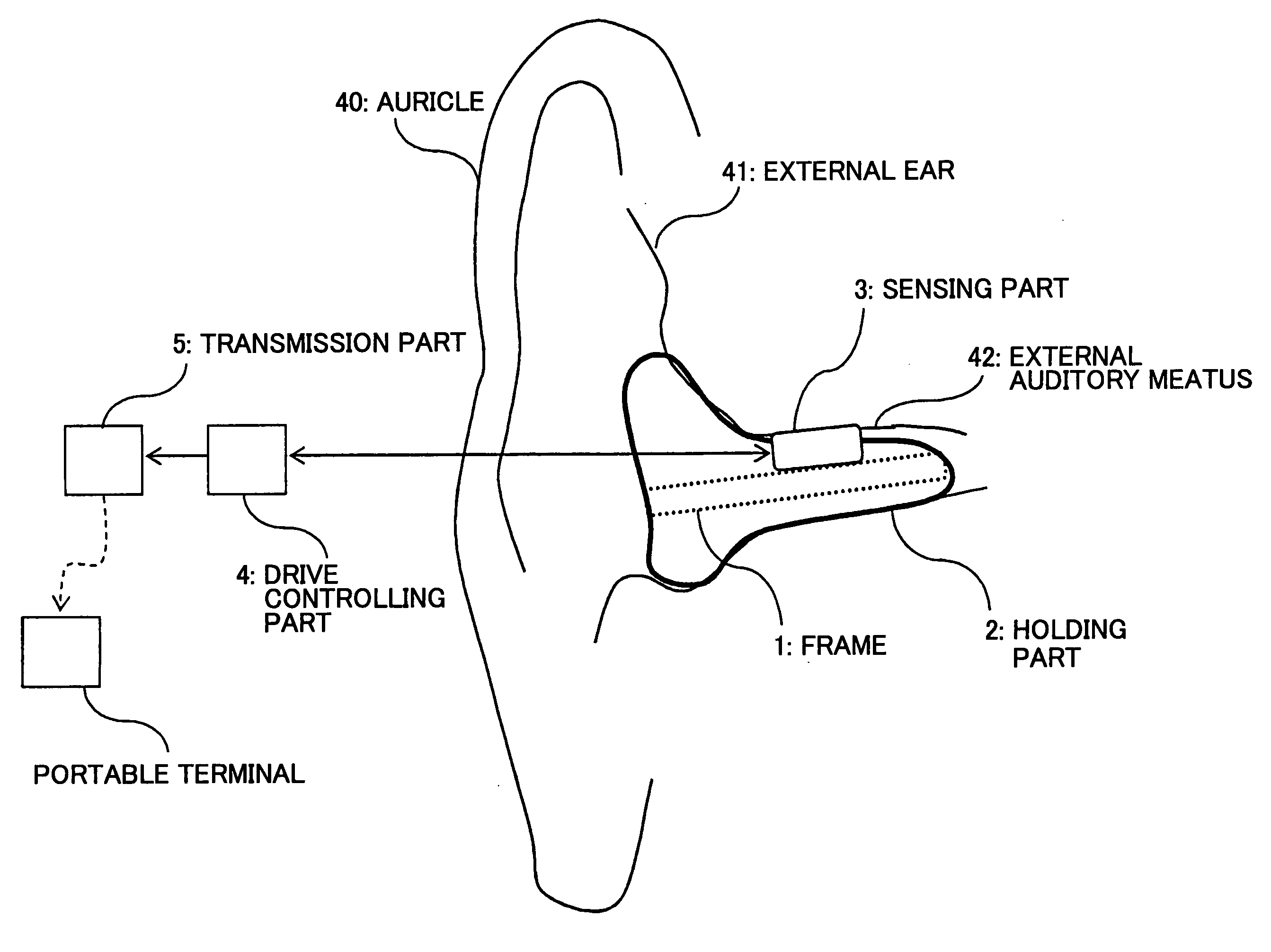
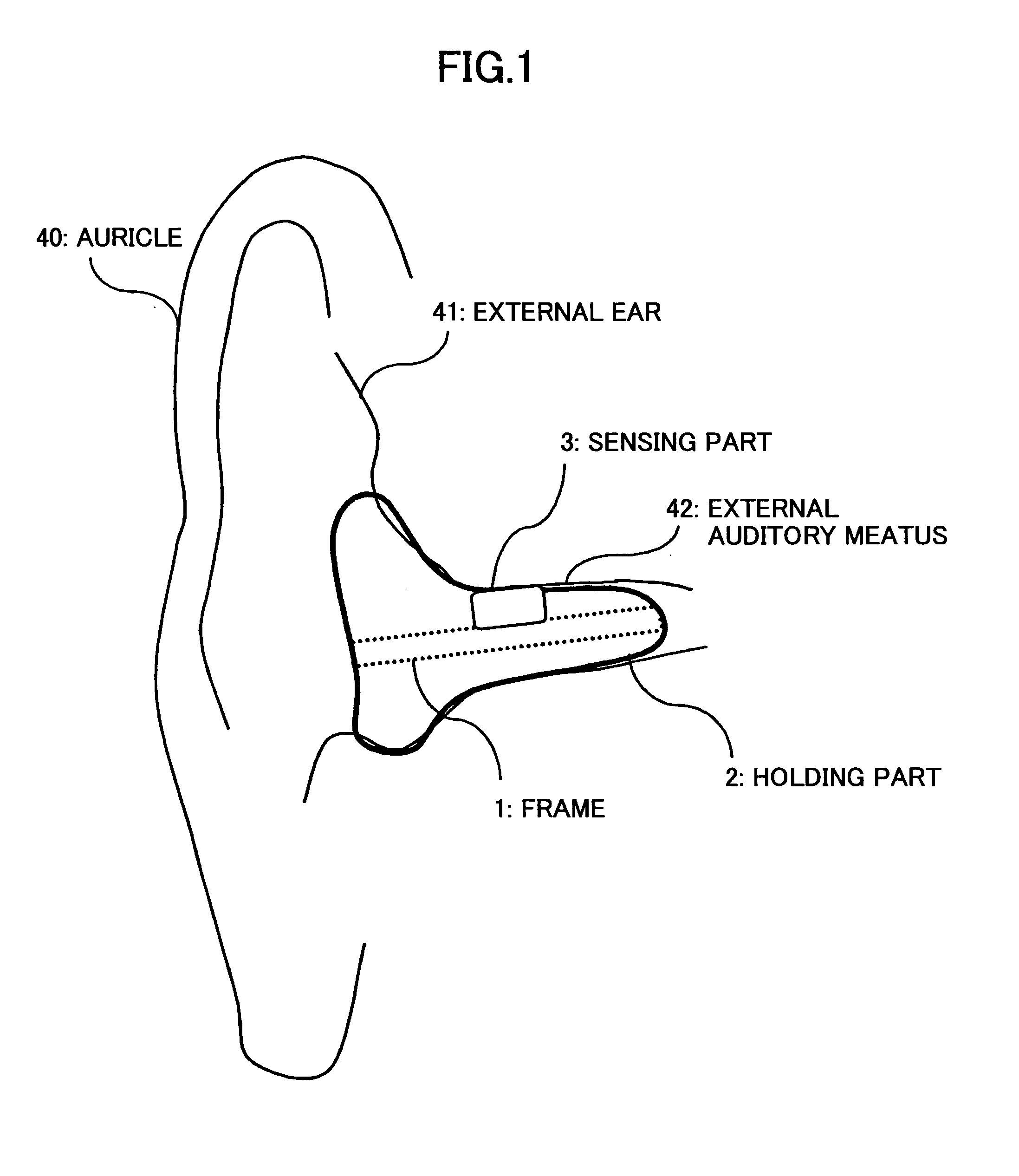
[0204]FIG. 1 shows a configuration of a living body information collecting apparatus in the embodiment 1-1 of the present invention. As shown in FIG. 1, the living body information collecting apparatus of this embodiment includes a hollow frame 1, a holding part 2 for holding the hollow frame 1 in the external auditory meatus, and a sensing part 3 that is attached to the hollow frame 1. FIG. 1 shows a state in which the holding part 2 is worn in the external ear 41. Reference signs in figures in each embodiment in this application are assigned independently for each embodiment unless otherwise stated.

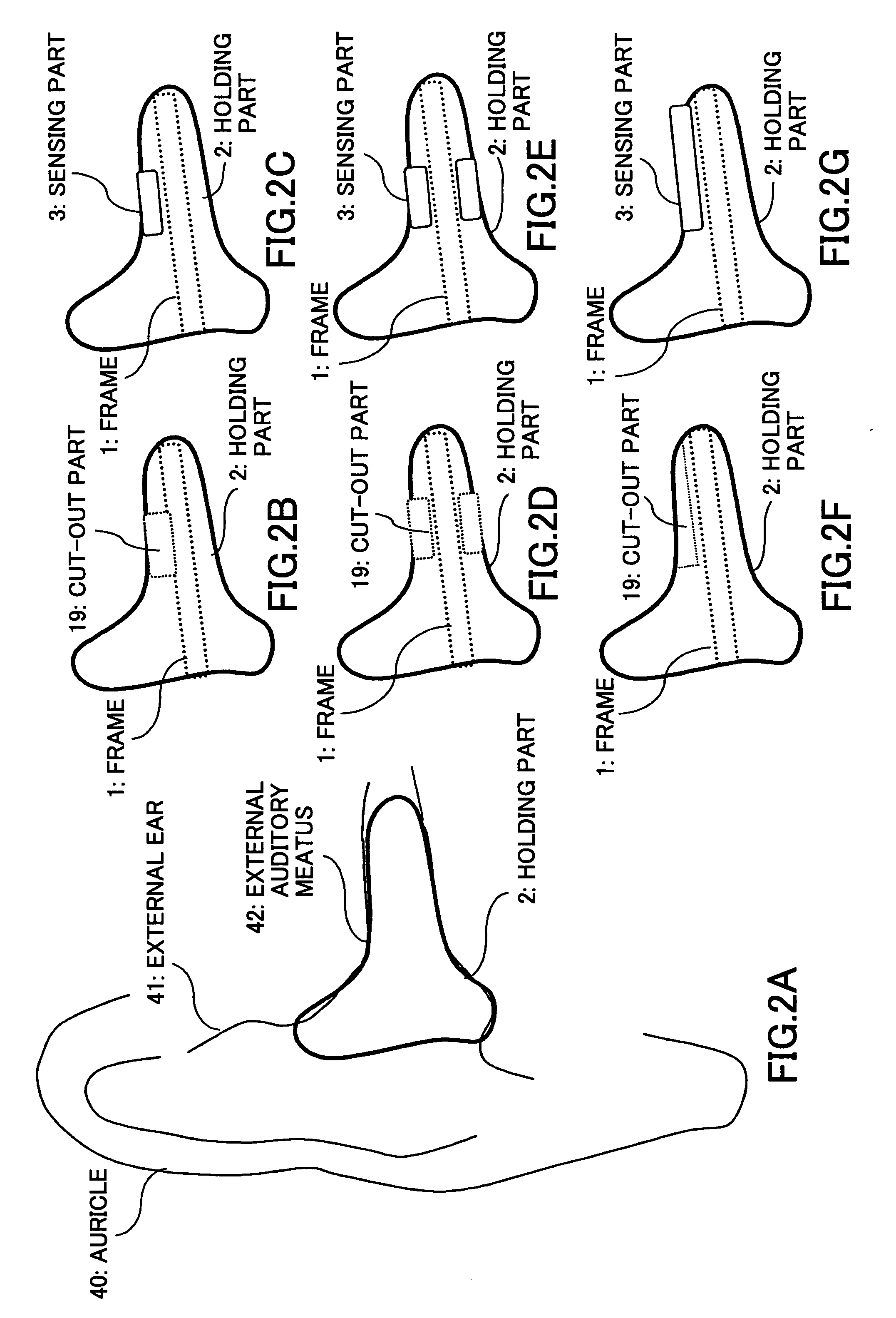
[0205] In the following, an example of a method for manufacturing the living body information collecting apparatus is described with reference to FIGS. 2A-2G each showing a section view of the living body information collecting apparatus. For manufacturing the living body information collecting apparatus of this embodiment, a shape of the external ear 41 and the external auditory meatu...

embodiment 1-2

[0215] In the following, this embodiment is described with reference to FIG. 5. FIG. 5 shows a configuration of the living body information collecting apparatus of this embodiment. As shown in FIG. 5, the living body information collecting apparatus of this embodiment includes a hollow frame 1, a holding part 2 for holding the hollow frame 1 to the external auditory meatus, a sensing part 3 attached to the hollow frame 1, and a drive controlling part 4 for performing drive control for the sensing part 3 and processing a signal from the sensing part. The drive controlling part 4 is connected to the sensing part 3 via the signal line.

[0216] Next, operation of the living body information collecting apparatus of this embodiment is described. The configuration including the hollow frame 1, the holding part 2 and the sensing part 3 is the same as that of the before-mentioned living body information collecting apparatus. A display part (not shown in the figure) for displaying a measuremen...


PUM


Abstract

An living body information collecting apparatus having a shape suitable for being worn in the external auditory meatus of the human body, and having a sensing part for collecting living body information from the external auditory meatus is provided. In addition, a blood-pressure meter is provided, wherein the blood-pressure meter includes: a frame part including a first arm and a second arm that are opposed to each other; a pressure applying part provided on at least one of a side of the first arm opposed to the second arm and a side of the second arm opposed to the first arm; and a detection part for detecting a pulse wave.

Description

TECHNICAL FIELD [0001] The present invention relates to an apparatus for detecting living body information at an ear part. BACKGROUND ART [0002] As the population is aging, response to lifestyle-related diseases of adults is becoming a large public problem. Especially, as to diseases related to high blood pressure, it is recognized that collecting blood pressure data for the long term is very important. From this viewpoint, various measurement apparatuses for measuring living body information such as the blood pressure are being developed. [0003] As a conventional technology for measuring living body information at an external ear part, there is a patient monitoring apparatus that is inserted into an external auditory meatus or other parts of the external ear for wearing continuously (refer to patent document 1, for example). This apparatus calculates pulse, pulse wave, electrocardiogram, body temperature, arterial oxygen saturation, blood pressure and the like based on received lig...

Claims


Application Information

Patent Timeline
Patent Type & Authority Applications(United States)
IPC IPC(8): A61B5/02A61B5/04A61B5/00A61B5/022
CPCA61B5/0002A61B5/02208A61B5/02225A61B5/6815A61B5/6816A61B5/6817A61B5/6838A61B2560/045A61B2562/0238A61B5/7405A61B5/02
Inventor UENISHI, YUJIHIGURASHI, EIJINAGANUMA, KAZUNORISUDO, SHOUICHISHIMADA, JUNICHIAIHARA, KIMIHISAKOIZUMI, HIROSHITATARA, NAOEHAYASHIDA, SHOICHIMINO, SHINJIOGUCHI, TAISUKETOCHIKUBO, OSAMU
Owner NIPPON TELEGRAPH & TELEPHONE CORP
Why Eureka
Try Eureka