Dynamic pressure sensing structure

a sensing structure and dynamic technology, applied in the field of dynamic pressure sensing structure, can solve the problems of affecting the frequency response of the microphone, the vibration of the diaphragm in the microphone correspondingly, and the limitations of the traditional microphone generally presented in the market, so as to facilitate the movement of the diaphragm, widen the frequency range, and increase the capacitance

Inactive Publication Date: 2006-04-13
IND TECH RES INST
View PDF6 Cites 9 Cited by
  • Summary
  • Abstract
  • Description
  • Claims
  • Application Information

AI Technical Summary

Benefits of technology

[0010] As compared to the diaphragm device in the prior condenser microphone where a deformed surface of the diaphragm device is approximate to a parabolic surface during the sensing status, the diaphragm(upper electrode) of the invention may be like a plate in outline, due to the creation of the flexible area. Therefore, the dynamic pressure sensing structure according to the present invention has a greater capacitance providing the same area of the diaphragm, and other same settings are given. When the actuation electrode is applied externally with a biased voltage, the upper electrode plate is caused to move downwards. Therefore, the capacitance formed between the upper and lower electrode plates may be different as the bias voltage varies and the biased voltage may also control sensitivity of instantaneous capacitance of the upper and lower electrode. In addition, boundary conditions of the upper electrode plate may change when the actuation electrode is applied externally with a biased voltage. This change may facilitate the movement of the diaphragm along the longitudinal direction due to the variation of the sound pressure of low frequencies and thus be more suitable for measurements of sounds of low frequencies compared to the currently existing sound measurement products. Therefore, the present invention provides the following advantages: 1. A lower cutoff frequency is provided so that a broadened frequency range is obtained. 2. Frequency adjustments are achieved. 3. Sounds of different frequency bands may be measured. 4. A higher sensitivity is achieved. 5. Pressure variations of weak sounds may be effectively detected. 6. Boundary capacitance may be effectively increased. 7. Smaller fundamental frequency is obtained. 8. A simpler outline of the structure is provided. 9. Sound pressure is easier to be balanced. To enable persons skilled in the art to further understand the objects, features and functions of the present invention, the present invention will be described in more detail with the accompanying drawings, as follows.

Problems solved by technology

However, the traditional microphones generally presented in the market have their limitations in sensing sounds with relatively high frequencies, such as the sound of vibrations of machines of middle frequencies, the closing sound of the heart mitral valves, the sound of turbulence flow of blood in blood vessels and the sound created by the rubbing between bone and ligament.
Specifically, when a sound is directed towards the condenser microphone, an acoustic wave corresponding to the sound has an action on the air and thus the air is compressed, which results in vibration of a diaphragm in the microphone correspondingly.

Method used


Image

  • Dynamic pressure sensing structure
  • Dynamic pressure sensing structure
  • Dynamic pressure sensing structure

Examples


Embodiment Construction

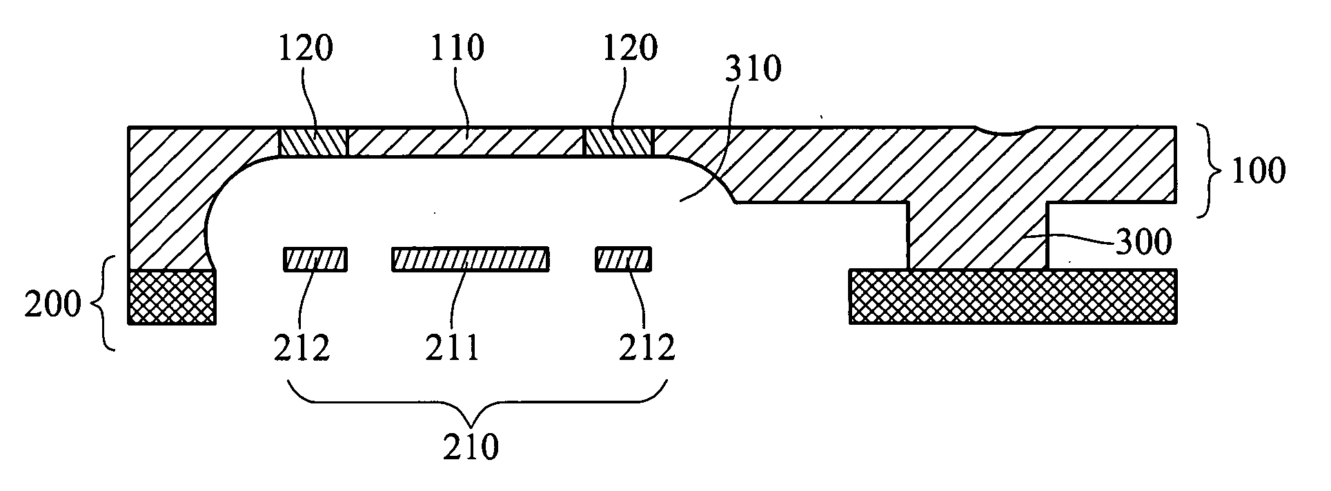
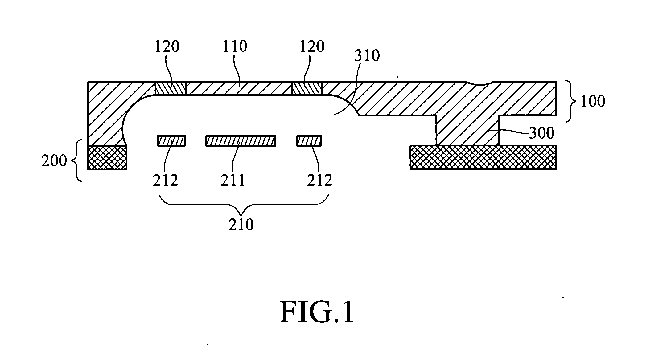
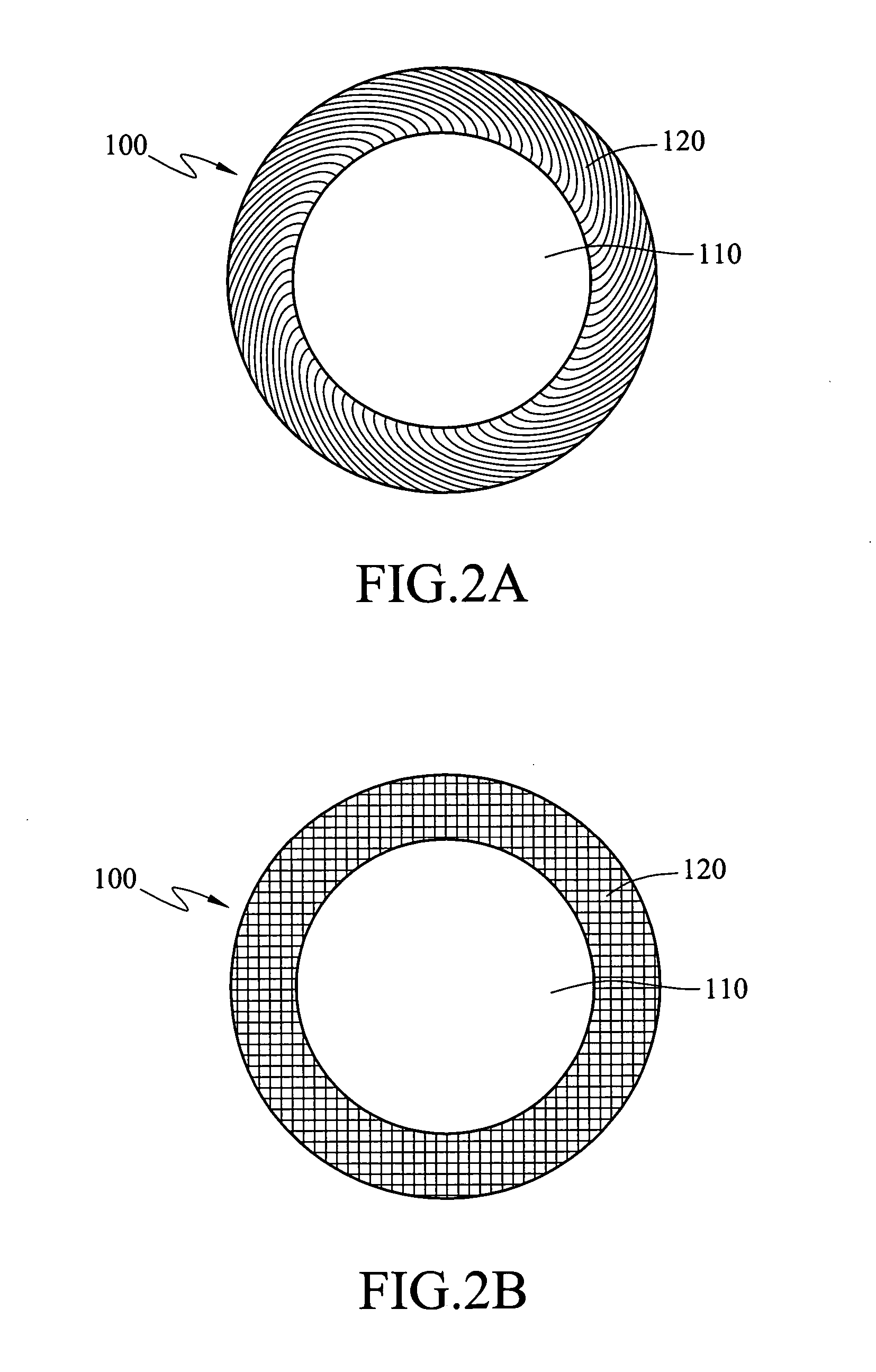
[0017]FIG. 1 is an enlarged cross sectional schematic view of a dynamic pressure sensing structure according to an embodiment of the present invention. As shown, the dynamic pressure sensing structure comprises an upper electrode plate 100, a spacer 300, a lower electrode plate 210 and a silicon wafer 200. The upper electrode plate 100 is connected to the spacer 300. The silicon wafer 200 comprises the lower electrode plate 210, consisting of a sensible electrode 211 and an actuation electrode 212. The lower electrode plate 210 is disposed below the upper electrode plate 100 and separated there from with a predetermined distance by the spacer 300 and thereby forms a cavity 310 correspondingly. The upper electrode plate 100 comprises a flat vibration area 110 and a flexible area 120 surrounding and connecting the flat vibration area 110. The lower electrode plate 210 comprising the sensible electrode 211 and the actuation electrode 212 is in an annular shape and surrounds the sensibl...


PUM


Abstract

A dynamic pressure sensing structure used in a condenser microphone includes an upper electrode plate, a lower electrode plate, a spacer and a substrate, wherein the upper and lower electrode plates are separated by the spacer and form a resonance cavity with the substrate. The upper electrode plate comprises a flat vibration area and a surrounding flexible area connected thereto. The lower electrode plate comprises a sensible electrode and an actuation electrode surrounding the sensible electrode. The plate is in connection with the flexible area so that a capacitor is formed between the sense area and the flat vibration area. The actuation electrode provides a polarization voltage to generate an electrostatic force, thereby attract the flexible vibration area to curve downwards so that the flat vibration area moves in a flat state and a distance between the flat vibration area and the sensible electrode is varied correspondingly.

Description

BACKGROUND OF THE INVENTION [0001] 1. Field of Invention [0002] The present invention relates to a dynamic pressure sensing structure and more particularly to a dynamic pressure sensing structure applied in a condenser microphone. [0003] 2. Related Art [0004] In the trend of ‘smaller and lighter’ in the modem-day markets, micro-electro-mechanical system (MEMS) technologies have been developed to meet these requirements. These MEMS have the advantages of miniature-permitted, batch manufacturing, low cost of used materials and high added values and thus are deemed as the most promising products in the future. [0005] Microphones are dynamic pressure sensors, which may sense very small variations like people's ears to sound. However, human's ears may react to only those sounds having specific frequency ranges owing to the physiological structures of people. Quite the contrary, the microphones with different structures may sense desired sounds with different frequency ranges. However, th...

Claims


Application Information

Patent Timeline
Patent Type & Authority Applications(United States)
IPC IPC(8): H04R25/00
CPCH04R19/04
Inventor SU, MAO-SHUNKUO, TSUNG-TERCHOU, YU-KONCHIOU, YII-TAY
Owner IND TECH RES INST
Why Eureka
Try Eureka