Method and Device for Measuring Electric Currents by Means of a Current Transformer

a current transformer and electric current technology, applied in measurement devices, instruments, voltage/current isolation, etc., can solve the problems of large hazard, uneven measured direct current, and inability to output suitable signals, so as to reduce the edge of steepness or reduce the edge, the reliability of the method is increased, and the effect of substantial simplification

Active Publication Date: 2014-06-12
EAN ELEKTROSCHALTANLAGEN
View PDF3 Cites 8 Cited by
  • Summary
  • Abstract
  • Description
  • Claims
  • Application Information

AI Technical Summary

Benefits of technology

[0043]Thereby, steep edges can be reduced or avoided advantageously in the measurement signal and the amplitude of high-order harmonics can be reduced to a small value, which usually brings substantial simplification in the analysis of the measurement of the mixed current.
[0044]According to another advantageous development, the magnitude of the generated negative ohmic resistance is controlled based on a determined incomplete compensation or over-compensation of the ohmic resistance of t

Problems solved by technology

This presents a problem and a major hazard when thresholds are exceeded during the operation of electrical equipment.
As with transformers, inductive current transformers are only sensitive to alternating electric currents, whereby, without further measures, a direct current does not output a suitable signal.
However, the measured direct current is not smooth.
A disadvantage of the known solutions with inductive current transformers is that the measurement of the DC residual cu

Method used


Image

  • Method and Device for Measuring Electric Currents by Means of a Current Transformer
  • Method and Device for Measuring Electric Currents by Means of a Current Transformer
  • Method and Device for Measuring Electric Currents by Means of a Current Transformer

Examples


Embodiment Construction

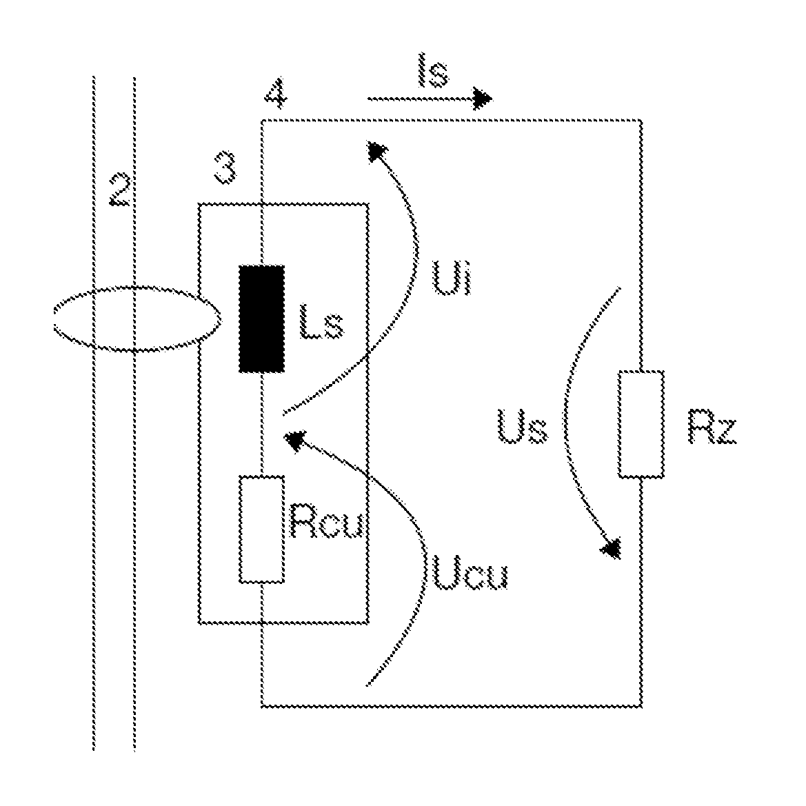
[0078]In FIG. 1 the circuit diagram of a current transformer according to the invention is shown with the resistance compensation in accordance with an embodiment of the invention. The coil 3 has a coil inductance Ls and a coil resistance Rcu. The current transformer monitors the primary conductor 2 for the presence of a differential current. The secondary current Is flows in the secondary circuit 4. The voltage drop Us of the coil is composed of the induction voltage Ui and the voltage drop Ucu over the ohmic coil resistance. For the differential current measurement by means of the current transformer in the secondary circuit 4, the ohmic coil resistance Rcu of the coil 3 is compensated by means of an active dipole forming the negative ohmic resistor Rz. In this way, a direct current component of a secondary current Is induced by a primary current 2 is maintained in the coil 3.

[0079]According to Kirchhoffs second law, it applies for the sum of all partial voltages in FIG. 1:

0=Ui+Uc...


PUM


Abstract

A method and a device for measuring electrical differential currents, which in addition to the alternating current component also contain a direct current component, by means of an inductive differential current transformer.
The known methods for measuring mixed currents require special current transformer designs with respect to the coil winding and magnetic core material and core number. The new method copes with the same current transformers that are common for measuring pure differential alternating currents.
According to the invention, the secondary coil (3) of the current transformer is controlled such that the magnetic flux (φ) linked with the secondary coil (3) inside the core remains constant, irrespective of the differential current and the secondary current (Is) required for this is measured. For this, on the one hand, the ohmic resistor (Rcu) of the secondary coil (3) is compensated in the secondary circuit (4) by an electronically produced, negative resistor (Rz), and on the other hand a defined magnetic flux is periodically restored, in that the saturation flux (φs) of the core is used as a reference point.

Description

BACKGROUND[0001]The invention relates to a method and a device for measuring electric currents by means of a current transformer. In particular, the invention relates to a method and a device for measuring the electric differential currents which, in addition to the alternating component, also contain a direct current component, and are thus mixed currents. The measurement of differential currents and / or residual currents is a major concern in the field of safety engineering of industrial plants and electrical equipment, in particular for the protection of people against electric shocks, but also for the protection of machinery, industrial equipment and electrical equipment against malfunction and damages due to unwanted or faulty current flows. An example of a possible occurrence of such unwanted current flows is so-called ground faults. In the case of a ground fault, an electric conductor forms an unintentional electrical connection to the ground potential, that is, there is a low...

Claims


Application Information

Patent Timeline
IPC IPC(8): G01R15/18
CPCG01R15/183G01R15/185
Inventor RATHSMANN, STEFAN
Owner EAN ELEKTROSCHALTANLAGEN
Why Eureka
Try Eureka