Removable inlet manifold for a medical/surgical waste collection system, the manifold including a driver for actuating a valve integral with the waste collection system

a waste collection system and intake manifold technology, applied in the direction of suction drainage containers, separation processes, applications, etc., can solve the problems of clogging the down line components of the system, reducing the extent of the suction tubing, clutter, etc., and achieving the effect of reducing the release of uncontained fluids

Active Publication Date: 2007-06-14
STRYKER CORP
View PDF26 Cites 75 Cited by
  • Summary
  • Abstract
  • Description
  • Claims
  • Application Information

AI Technical Summary

Benefits of technology

[0012] This invention is directed to a new and useful system for collecting surgical and medical waste. The system of this invention has an intake manifold to which suction tubes are connected. The manifold is

Problems solved by technology

This reduces the extent to which the suction tubing, which invariably also functions as operating room clutter, is present around the surgical personnel.
This is desirable because these solids can potentially clog the down line components of the system.
Use of the above system significantly reduces the extent to which medical/surgical personnel are exposed to potentially hazardous medical waste.
Nevertheless, there are some disadvantages associated with the known waste collection systems.
If the liquid is not immediately wiped off the manifold, it can potentially fall of the manifold and be added waste matter t

Method used


Image

  • Removable inlet manifold for a medical/surgical waste collection system, the manifold including a driver for actuating a valve integral with the waste collection system
  • Removable inlet manifold for a medical/surgical waste collection system, the manifold including a driver for actuating a valve integral with the waste collection system
  • Removable inlet manifold for a medical/surgical waste collection system, the manifold including a driver for actuating a valve integral with the waste collection system

Examples


Embodiment Construction

I. Overview

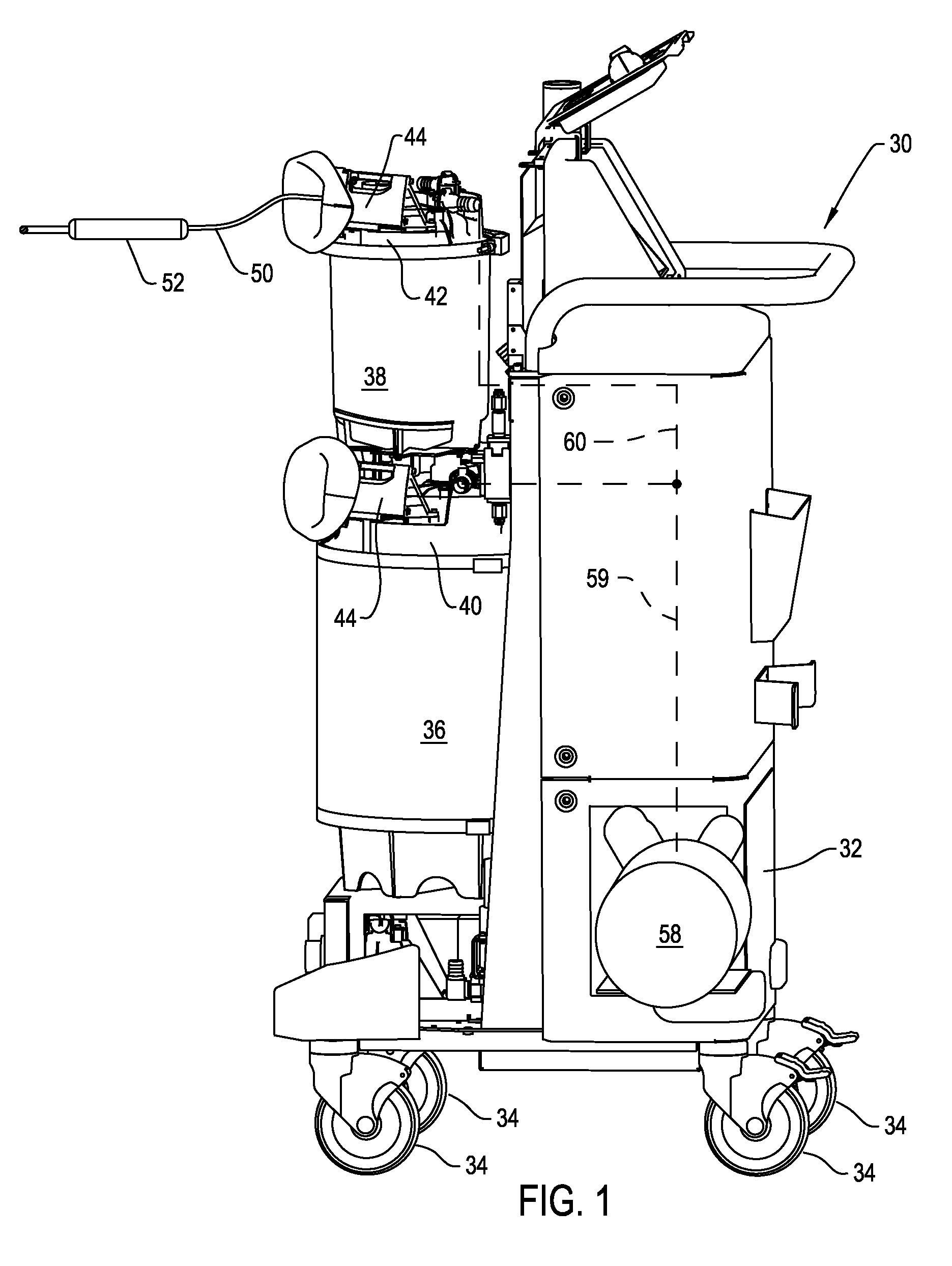
[0038]FIG. 1 illustrates a waste collection system 30 constructed in accordance with this invention. System 30, sometimes referred to as a mobile unit, includes a base 32. The cover and door assemblies that normally conceal the components are mobile unit 30 are not present in FIG. 1 so that these components can be seen. Wheels 34 attached to the bottom of the base 32 provide the system with mobility. Two canisters 36 and 38 are mounted to the base 32. A first one of the canisters, canister 36, has a relatively large interior volume, between approximately 10 and 40 liters. The second canister, canister 38, has a smaller volume, between approximately 1 and 10 liters. Each canister 36 and 38 has a cap 40 and 42, respectively.

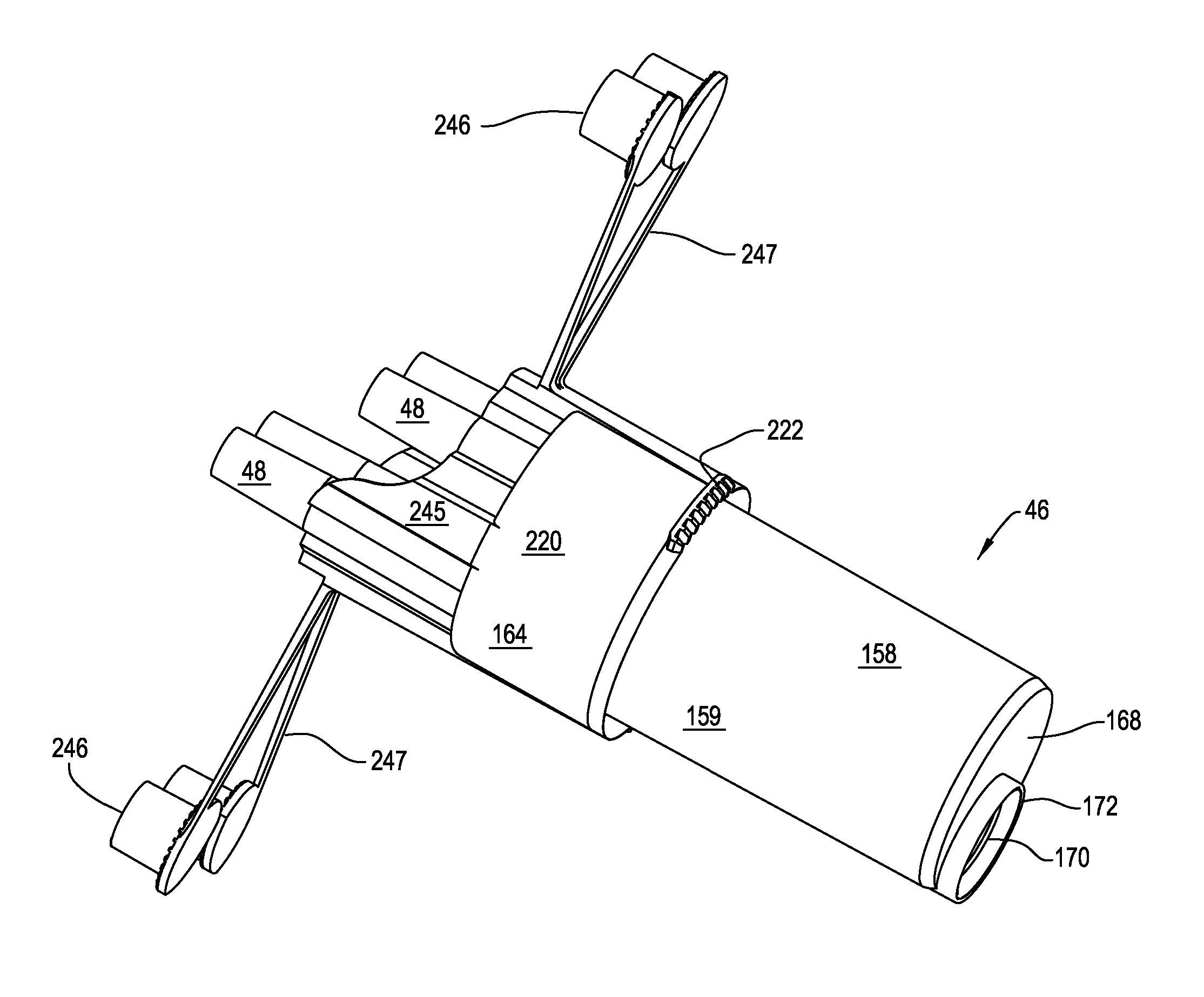
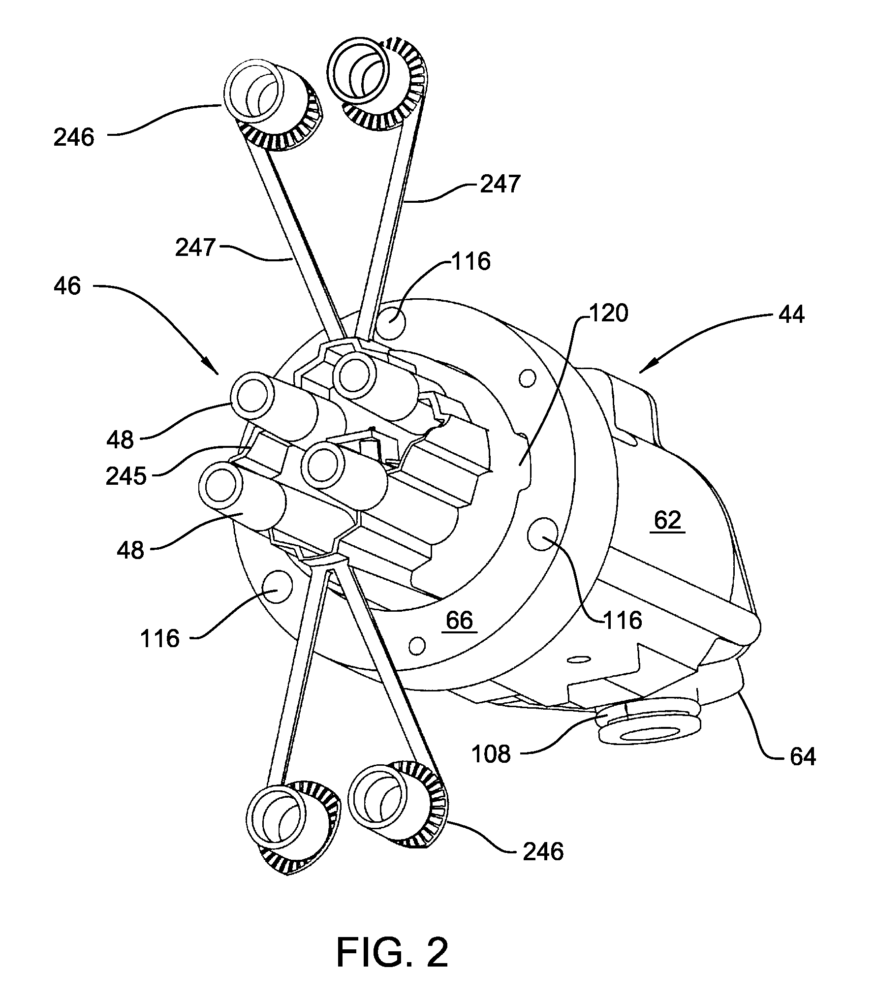
[0039] Attached to each canister cap 40 and 42 is a manifold receiver 44. A manifold 46, seen in FIGS. 2 and 3, is removably seated in each manifold receiver 44. As described below, each manifold 46 is formed with a number of fittings 48. Each fitting 4...


PUM

PropertyMeasurementUnit
Shapeaaaaaaaaaa

Abstract

A removable manifold for a medical/surgical waste collection system. The manifold is dimensioned to be mounted to a receiver integral with the system. The manifold includes a driver for engaging a complementary valve internal to the receiver. The valve regulates flow between the receiver and the down line components of the waste collection system. The valve is normally closed. When the manifold is fitted to the receiver the driver engages the valve so as move the valve to the open position. This allows fluid flow from the manifold and receiver to the downstream components of the system.

Description

RELATIONSHIP TO EARLIER FILED APPLICATION [0001] This application claims priority under 35 U.S.C. Sec. 119 from U.S. Provisional Patent Application No. 60 / 750,862 filed 14 Dec. 2005.FIELD OF THE INVENTION [0002] This invention relates generally to a system for collecting waste generated during a surgical procedure. More particularly, this invention relates to a waste collection system with a removable intake manifold that, when removed from the system, prevents the release of uncollected waste still in the manifold or the complementary receiver to which the manifold was attached. BACKGROUND OF THE INVENTION [0003] A byproduct of the performance of some medical and surgical procedures is the generation of liquid, semi-solid and solid waste. This waste includes body fluids, such as blood, and irrigating solution that are introduced to the body site at which the procedure is performed. Solid and semisolid waste generated during a procedure includes bits of tissue and small pieces of th...

Claims


Application Information

Patent Timeline
IPC IPC(8): A61M1/00
CPCA61M2205/125A61M1/0052A61M2205/7545A61M2205/7563A61B18/148A61B19/0248A61B19/0287A61B19/0288A61B2019/025A61B2019/0254A61M1/0001A61M1/0005A61M1/0023A61M1/0031A61M1/0049A61M1/0056A61M1/0058A61M1/0027A61M1/0007A61M1/0033A61M1/0035A61M1/005A61M2205/3331A61M1/784A61M1/79A61M1/84A61M1/782A61M1/76A61M1/60A61M1/71A61M1/77A61B2050/185A61B50/10A61B50/13A61B50/36A61B50/362Y10T137/87965Y10T137/87571Y10T137/87676A61M1/631A61M1/732A61M1/63A61M1/742A61M1/743A61M1/78A61M1/74A61M3/0201A61M1/72A61B50/00A61M1/00A61M1/92
Inventor MURRAY, SEAN A.HERSHBERGER, DAVIDLALOMIA, BRENT S.REASONER, STEPHENISHAM, STEPHEN
Owner STRYKER CORP
Why Eureka
Try Eureka