Surface guided knee replacement

a knee joint and surface guided technology, applied in knee joints, prostheses, medical science, etc., can solve the problems of reducing the maximum flexion angle achieved, altering the mechanics of the patella, and not giving the ‘feeling of a normal knee', and achieve the effect of low conformity

Inactive Publication Date: 2007-06-14
NEW YORK UNIV
View PDF49 Cites 93 Cited by
  • Summary
  • Abstract
  • Description
  • Claims
  • Application Information

AI Technical Summary

Benefits of technology

[0013] If a total knee is designed for resection of both of the cruciate ligaments, the criterion can be simplified to the requirement that ‘the neutral path and the laxity of the total knee itself are the same as that of an average knee specimen.’ That is the criterion -applied to the embodiment described here.
[0014] The major design features embodied are (1) the anterior medial recess on the femoral component interfacing with a pad on the anterior of the tibial surface, (2) relatively conforming medial bearing surfaces, (3) low conformity lateral bearing surfaces, and (4) a central post projecting from the center of the tibia, articulating inside a cupola in the center of the femoral component.
[0015] The combination of the above features provide progressive posterior displacement of the lateral femoral condyle from about sixty degrees flexion to maximum flexion, only a small posterior displacement of the medial femoral condyle, but some rotational laxity about the neutral position at all angles of flexion.

Problems solved by technology

The kinematic abnormalities may reduce the maximum flexion angle achieved, reduce the efficiency of the quadriceps, alter patella mechanics, and not give the ‘feeling of a normal knee’ (Pritchett 2004).
This criterion has the limitation that an off-the-shelf total knee needs to be based on ‘average’ geometry and kinematics, and hence there may not be an exact match for any particular knee.

Method used


Image

  • Surface guided knee replacement
  • Surface guided knee replacement
  • Surface guided knee replacement

Examples


Embodiment Construction

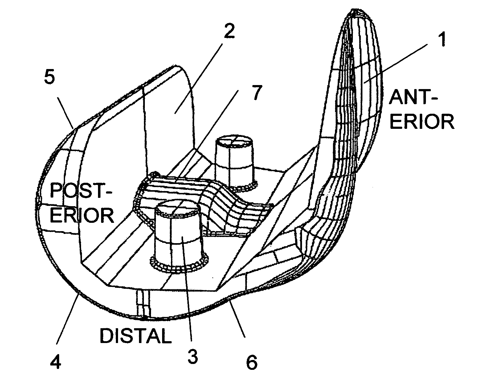
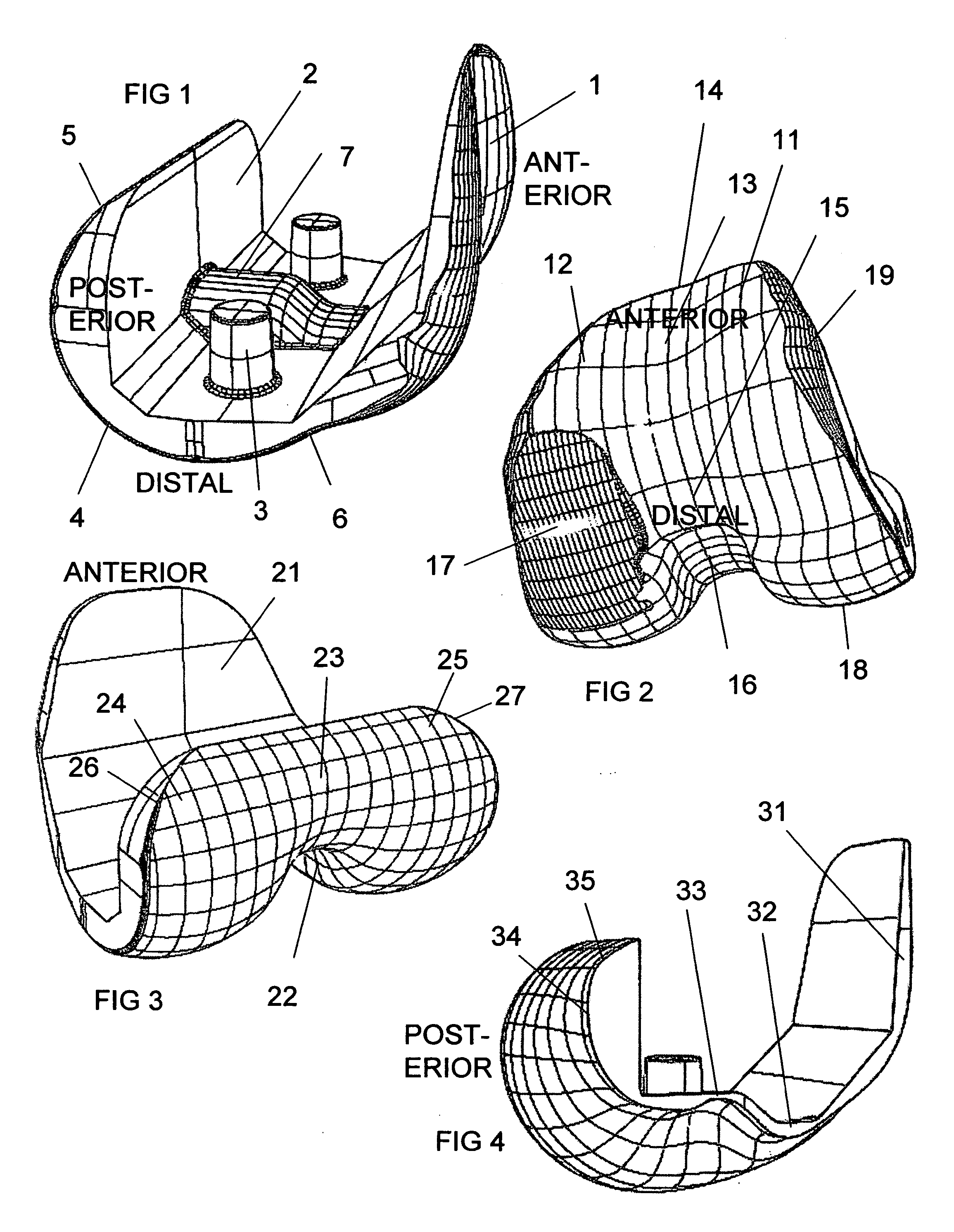
[0033] Femoral Component (FIGS. 1 thru 4)

[0034]FIG. 1 shows a side view of the femoral component with an anterior portion to the right and posterior portion to the left. The general shape of the femoral component resembles that of designs which are in common use in orthopedics. The shape is designed to replace the bearing surfaces of the distal femur and to fix rigidly on to the bone.

[0035] A patella flange 1 is at the anterior portion of the femoral component. The interior surface of the component 2 has five facets, which fit against the prepared surface of the bone which is cut likewise. Fixation to the bone can be by cement or by a bone ingrowth surface. In either case, augmentation of fixation can be provided by fixation pegs 3.

[0036] The bearing surface 4 which articulates with the tibia runs from the distal portion of the femoral component to the posterior portion. For contact in high flexion, the bearing surface 5 preferably has a reduced radius of curvature to facilitate ...


PUM


Abstract

An artificial knee joint that includes a femoral component with a specially shaped bearing surface and a tibial component, whose surface interacts with the femoral surfaces. The interaction provides for the motion and stability characteristics of the anatomic knee. The interaction between the femoral and tibial surfaces is such that as the knee is flexed to maximum, the femoral component moves posteriorly on the tibial surface, more so on the lateral side than on the medial side. This is accomplished by the interaction of a projecting tibial post inside a cupola in the center of the femoral component, and by the saggital radius on the medial side being smaller than that on the lateral side. The prevention of anterior sliding of the femur on the tibia in early flexion is accomplished by the interaction between a distal-anterior recess on the medial side of the femur and an apposing raised pad on the tibial surface. Rotational laxity at all angles is allowed by the presence of only one recess pad and by non-conforming femoral-tibial surfaces on the lateral side.

Description

BACKGROUND [0001] In an average person, the motion of the knee between the femur and the tibia is not unique. It varies with the person's muscle activity and the functions being performed. [0002] Numerous studies have been performed on both the living knee and cadaveric specimens which determined general characteristics of knee motion, including a neutral path, and deviations about the neutral path which occur when shear forces or torques are superimposed. [0003] Reference data for the normal knee has been obtained using fluoroscopy (Dennis, Komistek et al, 2001), as well as in a variety of other ways on both the living knee and in cadavers. It is now known that during flexion, the medial femoral condyle remains at an almost constant position on the tibial surface, whereas the lateral femoral condyle is displaced posteriorly, off the very back of the tibia in extreme flexion (Iwaki, Pinskerova et al, 2000; Nakagawa, Kadoya et al, 2000). [0004] This movement pattern has been describe...

Claims


Application Information

Patent Timeline
Patent Type & Authority Applications(United States)
IPC IPC(8): A61F2/38
CPCA61F2/3859
Inventor WALKER, PETER STANLEY
Owner NEW YORK UNIV
Why Eureka
Try Eureka