System, method, and apparatus for diverterless hypersonic inlet for integrated turbojet and ram-scramjet applications

Active Publication Date: 2007-06-14
LOCKHEED MARTIN CORP
View PDF5 Cites 9 Cited by
  • Summary
  • Abstract
  • Description
  • Claims
  • Application Information

AI Technical Summary

Benefits of technology

[0007] One embodiment of a system, method, and apparatus for diverterless hypersonic inlets (DHI) offers solutions that incorporate favorable air flow characteristics for high speed (e.g., Mach 3+) air-breathing propulsion systems. The DHI shape thins the boundary layer for engines that traditionally operate above Mach 3, thereby allowing them to work

Problems solved by technology

The long and narrow shape of DHI designs also improves transonic drag, which is a

Method used


Image

  • System, method, and apparatus for diverterless hypersonic inlet for integrated turbojet and ram-scramjet applications
  • System, method, and apparatus for diverterless hypersonic inlet for integrated turbojet and ram-scramjet applications
  • System, method, and apparatus for diverterless hypersonic inlet for integrated turbojet and ram-scramjet applications

Examples


Example

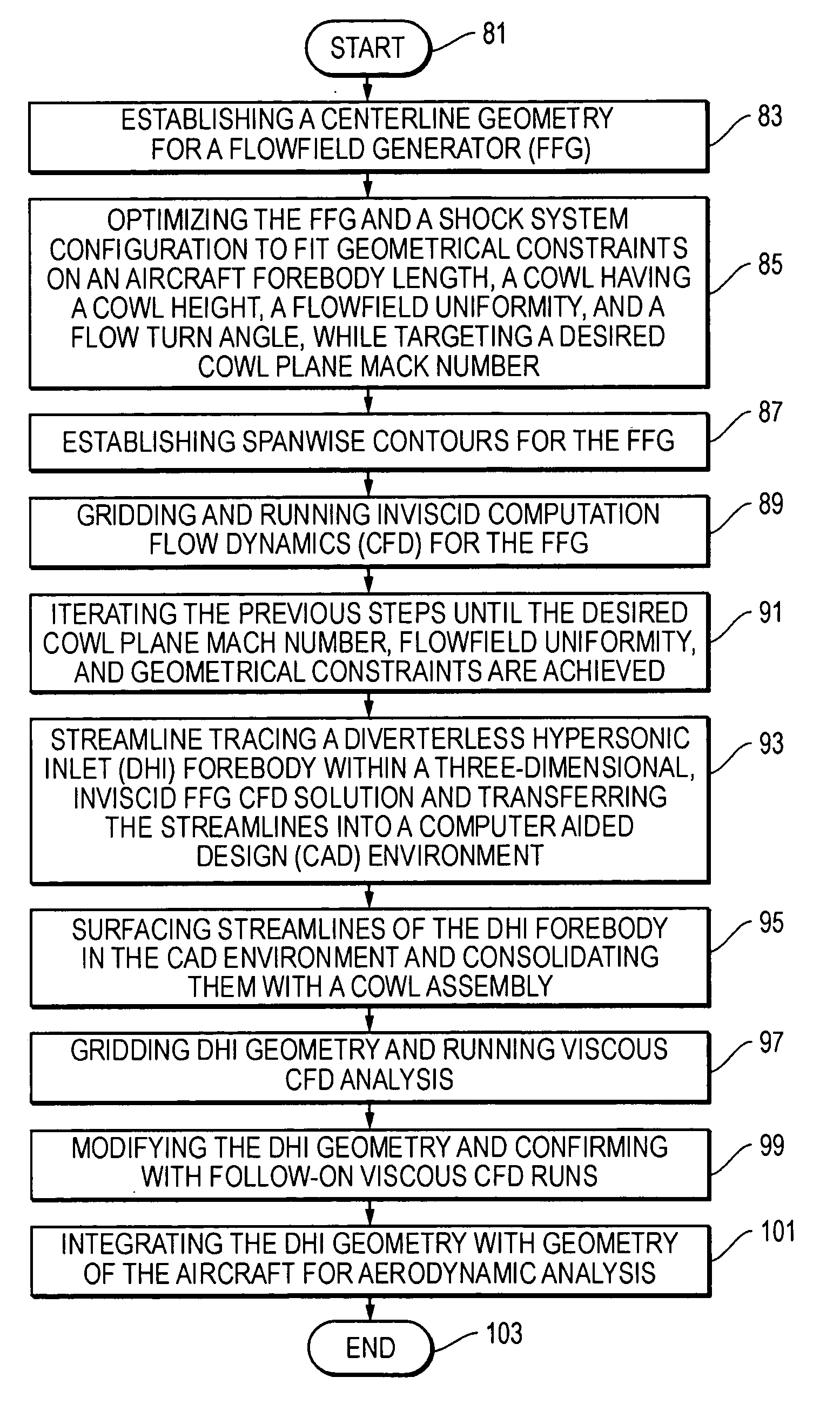
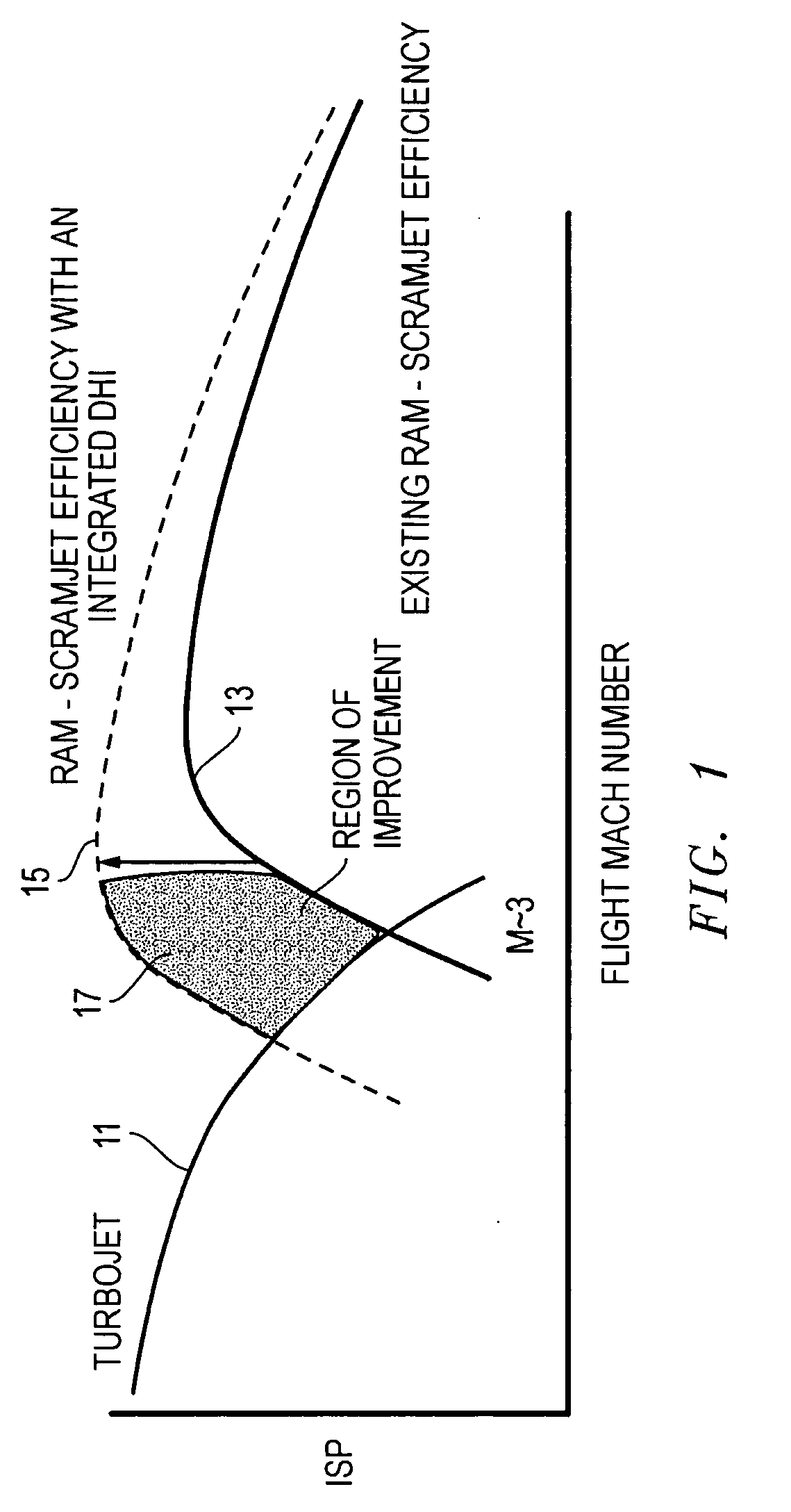
[0021] Referring to FIGS. 1-8, various embodiments of a system, method, and apparatus for a diverterless hypersonic inlet (DHI) constructed in accordance with the present invention are shown. As shown in FIG. 1, the performance 11 of aircraft with conventional turbojet engines deteriorates quickly as flight speed approaches Mach 3. Similarly, the performance 13 of conventionally configured ramjets and scramjets is also weak at flight speeds in the vicinity of Mach 3. However, a high speed aircraft configured with a DHI constructed in accordance with the present invention has a performance 15 with a significantly enhanced region of improvement 17 over conventional inlet designs. The turbojet, ramjet, and scramjet engine applications for the DHI of the present invention include flight speeds of approximately Mach 2.5 to 10.

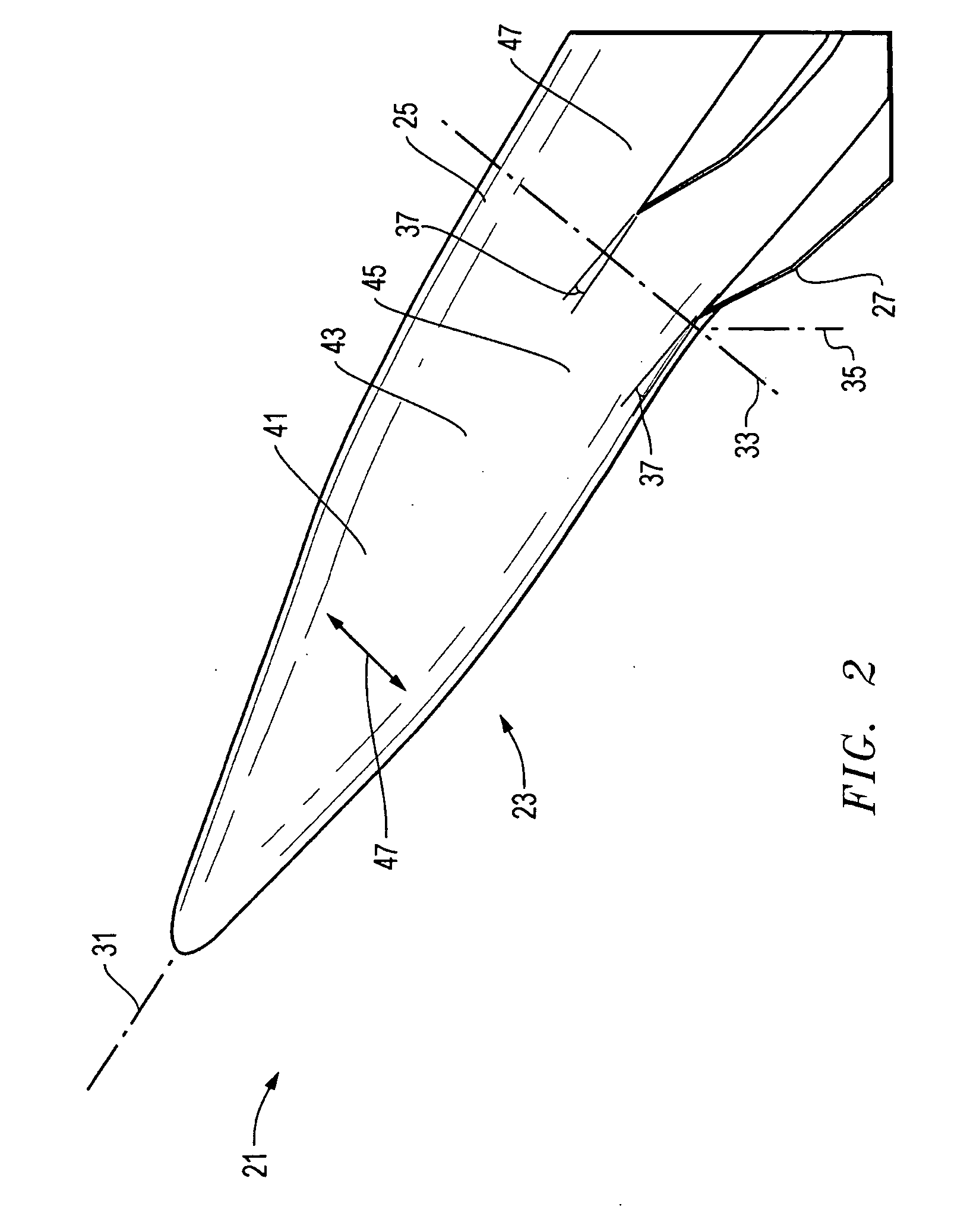
[0022]FIG. 2 illustrates an aircraft 21 with one embodiment of a DHI design 23 for processing hypersonic airflow. The DHI 23 extends along the forebody and incorpo...


PUM


Abstract

A diverterless hypersonic inlet (DHI) for a high speed, air-breathing propulsion system reduces the ingested boundary layer flow, drag, and weight, and maintains a high capture area for hypersonic applications. The design enables high vehicle fineness ratios, low-observable features, and enhances ramjet operability limits. The DHI is optimized for a particular design flight Mach number. A forebody segment generates and focuses a system of multiple upstream shock waves at desired strengths and angles to facilitate required inlet and engine airflow conditions. The forebody contour diverts boundary layer flow to the inlet sides, effectively reducing the thickness of the boundary layer that is ingested by the inlet, while maintaining the capture area required by the hypersonic propulsion system. The cowl assembly is shaped to integrate with the forebody shock system and the thinned boundary layer region.

Description

[0001] This patent application is subject to U.S. Air Force contract No. F33615-00-D-3053. The Government has certain rights in this invention.BACKGROUND OF THE INVENTION [0002] 1. Technical Field [0003] The present invention relates in general to air craft engines and, in particular, to an improved system, method, and apparatus for a diverterless hypersonic inlet for integrated turbojet and ram-scramjet aircraft jet engine applications. [0004] 2. Description of the Related Art [0005] Boundary layer diverters using splitter plate and wedge geometries are traditionally employed to reduce or eliminate boundary layer thickness upstream from the inlets of airbreathing propulsion systems at Mach 1 to Mach 2+. The high drag and weight of such devices has been overcome in the past with more thrust (which required bigger engines), more engines, or the additional use of afterburners. These designs result in yet more weight, less vehicle payload capacity, higher fuel consumption, and / or other...

Claims


Application Information

Patent Timeline
IPC IPC(8): G06F17/10
CPCG06F17/5009G06F17/5095G06F2217/16Y10T137/0536G06F30/15G06F2111/10G06F30/20Y02T90/00
Inventor LELAND, BRADLEY C.KLINGE, JOHN D.LUNDY, BRIAN F.
Owner LOCKHEED MARTIN CORP
Why Eureka
Try Eureka