
Methods and apparatus for coupling honeycomb seals to gas turbine engine components

a technology for gas turbine engines and honeycomb seals, applied in mechanical equipment, machines/engines, manufacturing tools, etc., can solve the problems of limiting the useful life of honeycomb seals, increasing the risk of hammer blowing,

Inactive Publication Date: 2007-06-21
GENERAL ELECTRIC CO
View PDF25 Cites 3 Cited by
  • Summary
  • Abstract
  • Description
  • Claims
  • Application Information

AI Technical Summary

Problems solved by technology

However, repeated hammering across the honeycomb seal track may damage the honeycomb or the seal track, may increase the risk of hammer blow pinch, and / or may limit the useful life expectancy of the honeycomb seal.

Method used


Image

  • Methods and apparatus for coupling honeycomb seals to gas turbine engine components
  • Methods and apparatus for coupling honeycomb seals to gas turbine engine components
  • Methods and apparatus for coupling honeycomb seals to gas turbine engine components

Examples


Embodiment Construction

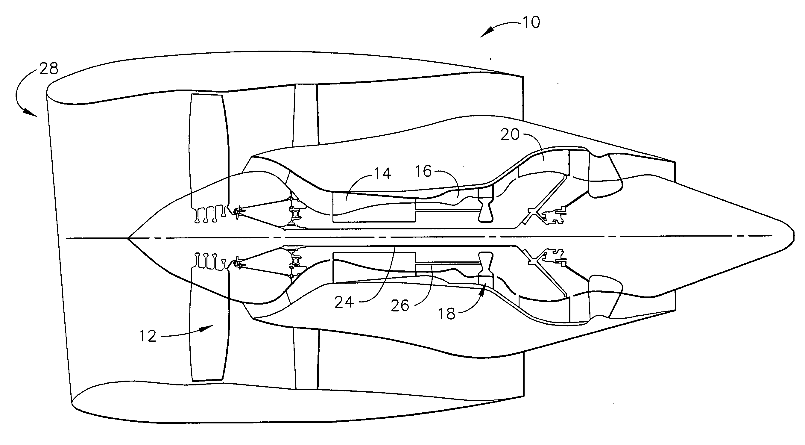
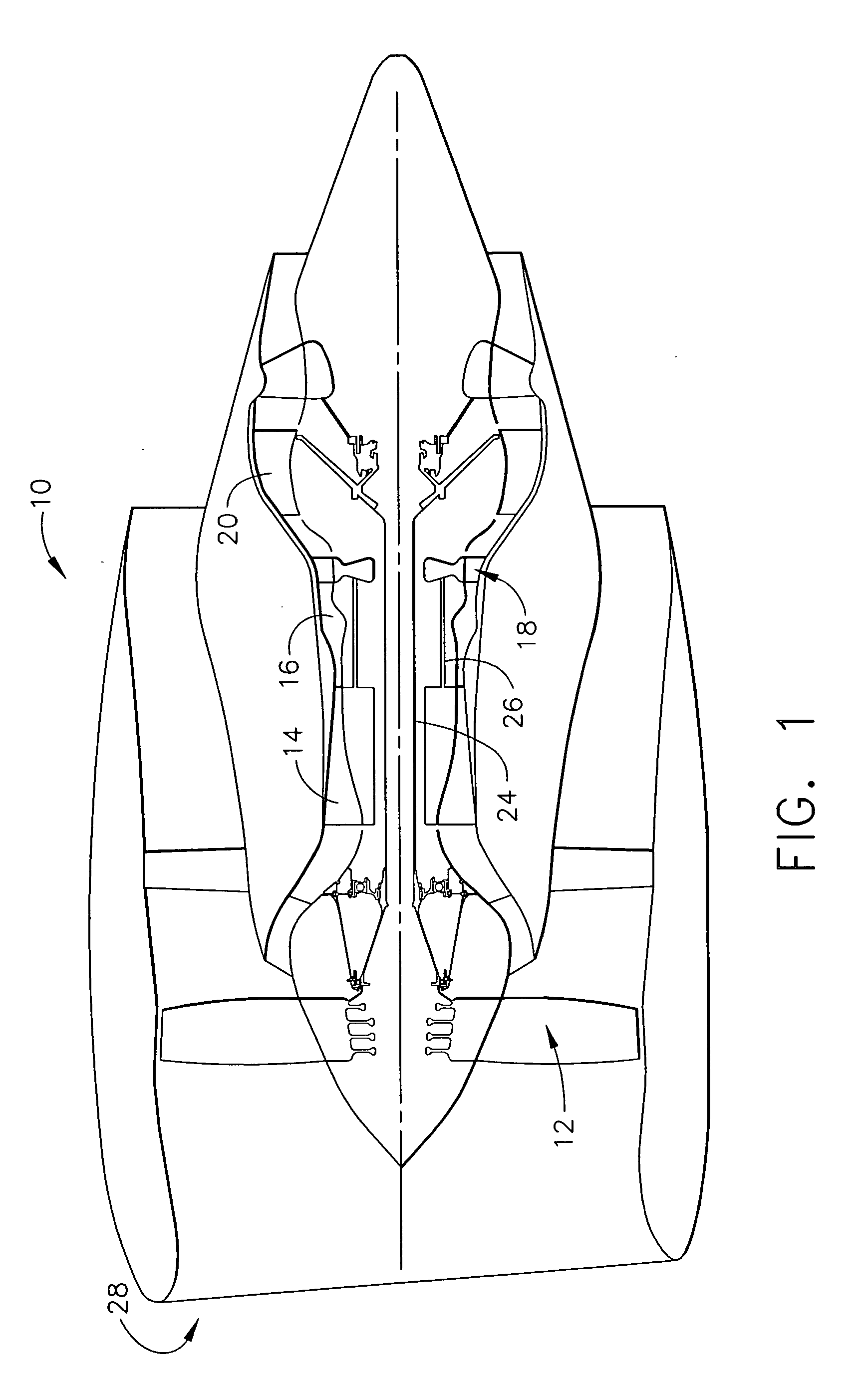
[0014]FIG. 1 is a schematic illustration of an exemplary gas turbine engine 10. Engine 10 includes a low pressure compressor 12, a high pressure compressor 14, and a combustor assembly 16. Engine 10 also includes a high pressure turbine 18, and a low pressure turbine 20 arranged in a serial, axial flow relationship. Compressor 12 and turbine 20 are coupled by a first shaft 24, and compressor 14 and turbine 18 are coupled by a second shaft 26.

[0015] In operation, air flows through low pressure compressor 12 from an upstream side 28 of engine 10. Compressed air is supplied from low pressure compressor 12 to high pressure compressor 14. Compressed air is then delivered to combustor assembly 16 where it is mixed with fuel and ignited. Combustion gases are channeled from combustor 16 to drive turbines 18 and 20.

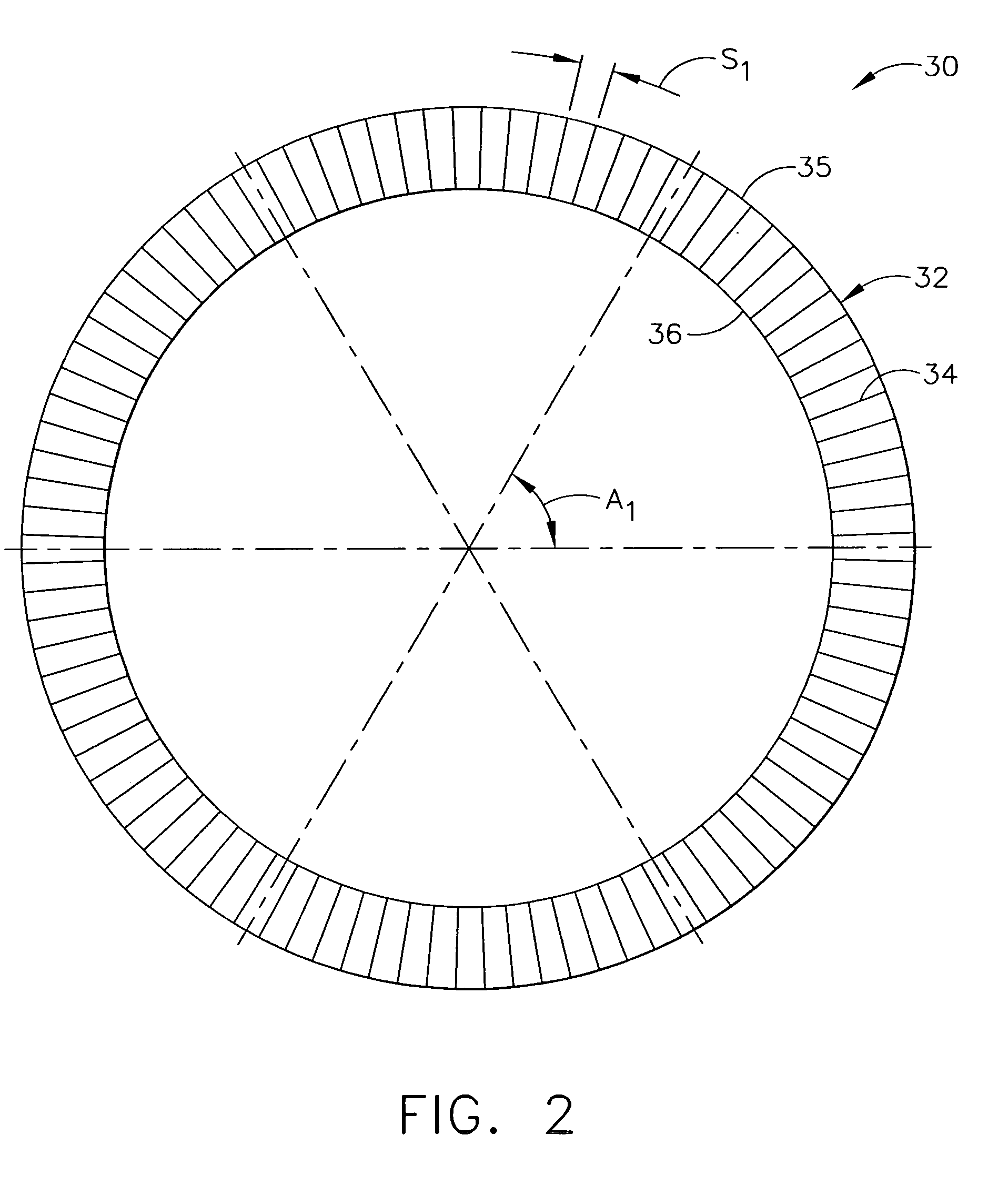
[0016]FIG. 2 is a schematic end view of an exemplary stator vane assembly 30 that may be used with gas turbine engine 10 (shown in FIG. 1). High pressure compressor 14 defines a...


PUM

PropertyMeasurementUnit
Angleaaaaaaaaaa
Radiusaaaaaaaaaa
Widthaaaaaaaaaa

Abstract

A method for assembling a gas turbine engine is provided. The method includes providing a vane sector and a honeycomb seal. The method further includes coupling the honeycomb seal to the vane sector utilizing a hydraulic tool.

Description

BACKGROUND OF THE INVENTION [0001] This invention relates generally to gas turbine engines and, more particularly, to methods and apparatus for coupling honeycomb seals to gas turbine engine components. [0002] Honeycomb seals are widely used in gas turbine engine applications. For example, at least some known gas turbine engines include at least one row of rotor blades that is radially inward from a plurality of honeycomb seals within cavities formed within a surrounding stator vane assembly. At least some known honeycomb materials are installed into a gas turbine engine via a manual crimping process to fixed vane sector components, for example. During break-in engine operations, seal teeth located on a first rotatable annular member cut grooves or channels into the honeycomb seals located on a second member having a different rotational speed than that of the first member. The channels cut by the seal teeth define an operating clearance between the seal teeth and the honeycomb mate...

Claims


Application Information

Patent Timeline
IPC IPC(8): B21D53/00
CPCB25B27/14F01D25/246Y10T29/4932F05D2240/11Y10T29/49549F16J15/444
Inventor AHTI, ROBERT ALLANALEXANDER, ALBERT ARTHURCAMPBELL, ALEXANDER KENNETH
Owner GENERAL ELECTRIC CO
Learn More