Rifle scope with adjustment knob having multiple detent forces

Active Publication Date: 2007-06-21
DOWN RANGE SOLUTIONS GRP LLC
View PDF3 Cites 52 Cited by
  • Summary
  • Abstract
  • Description
  • Claims
  • Application Information

AI Technical Summary

Benefits of technology

[0006] An adjustment knob with more clicks per degree or minute of angle will provide finer control, which is especially useful at greater distances. A coarser detent arrangement will provide less precision, but makes it easier for the shooter to count the number of clicks. For a distant target requiring a substantial adjustment to compens

Problems solved by technology

This slows the adjustment process, and is prone to errors that can be critical.
Such errors can accumulate as the shooter

Method used


Image

  • Rifle scope with adjustment knob having multiple detent forces
  • Rifle scope with adjustment knob having multiple detent forces
  • Rifle scope with adjustment knob having multiple detent forces

Examples


Example

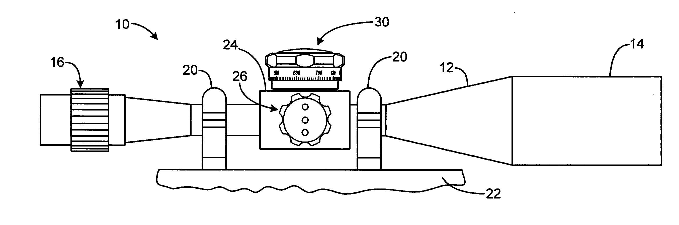
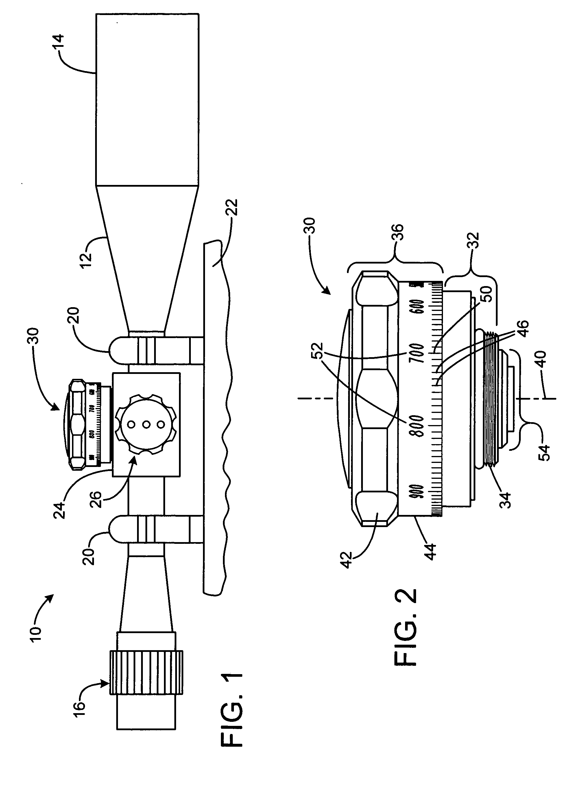
[0012]FIG. 1 shows a rifle telescope 10 having a tubular body 12 with a forward objective lens 14, and an eyepiece 16 at the opposite end. The telescope 10 is mounted by rings 20 to the frame 22 of a rifle. A central housing 24 is located at an intermediate position on the body, and supports a windage knob 26 and an elevation knob 30. An optical element such as a prism or lens assembly (not shown) is located within a bore defined by the body, and is shifted in position in response to rotation of the knobs, to adjust the aiming point of the reticle. This allows the user to zero the scope, to compensate for wind drift, and to compensate for bullet drop over distance.

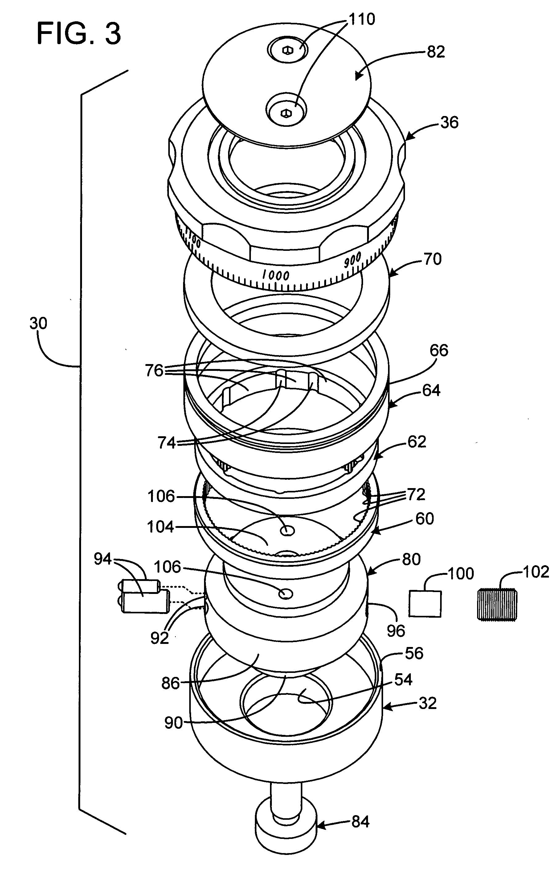
[0013]FIG. 2 shows the elevation knob 30 in greater detail. A body portion 32 is fixed to the housing 24 when assembled, by way of threads 34 that engage a threaded bore in the housing. A rotatable knob 36 rotates with respect to the housing about a vertical axis 40. The knob has a grip portion 42 that is knurled or textu...


PUM


Abstract

A rifle scope has a body with a number of optical elements. An adjustment knob is rotated we connected to the body and interacts with at least one of the optical elements to provide an image shift in response to rotation of the knob. A detent mechanism interacts with the knob, and has a number of detent positions. Many of the detent positions have a first detent force, and a selected subset the detent positions have a greater second force. The selected subset of detent positions may correspond to selected major distance intervals.

Description

REFERENCE TOP RELATED APPLICATION [0001] This application relates to Provisional Application for Patent Ser. No. 60 / 597,849, filed Dec. 21, 2005, entitled “Dual Detent Elevation Knob for Use on Riflescopes.”FIELD OF THE INVENTION [0002] This invention relates to rifle scopes, and more particularly to adjustment knobs for rifle scopes. BACKGROUND AND SUMMARY OF THE INVENTION [0003] Rifle scopes are provided with crosshairs or other reticle designs to provide an indication of an aiming point, where a bullet is expected to impact. Because bullets follow the path of an arc, the point of impact varies based on distance. Therefore, rifle scopes are normally equipped with adjustment knobs to shift optical components within the rifle scope to compensate for bullet drop. If a target distance is known, a knob adjustment is made based upon the predicted trajectory of the bullet. For a given type of ammunition, and elevation adjustment knob may be marked with distance markings to indicate to th...

Claims


Application Information

Patent Timeline
IPC IPC(8): F41G1/38
CPCF41G1/38F41G1/44
Inventor WILLIAM, JOHN B. IIIBAROLDI, NICK A.
Owner DOWN RANGE SOLUTIONS GRP LLC
Why Eureka
Try Eureka