Display driving method and circuit, LED display panel and display device

A display driver and circuit technology, applied in static indicators, instruments, etc., can solve problems such as serious luminous consistency problems, and achieve precise wavelength correction, luminous brightness display, and fine control.

Pending Publication Date: 2022-06-21
XIAN TIBORS ELECTRONIC TECH CO LTD
View PDF0 Cites 0 Cited by
  • Summary
  • Abstract
  • Description
  • Claims
  • Application Information

AI Technical Summary

Problems solved by technology

However, there are also some process problems in COB packaging, and because the LED light points before COB packaging have not undergone strict light separation and color separation, the problem of lu

Method used


Image

  • Display driving method and circuit, LED display panel and display device
  • Display driving method and circuit, LED display panel and display device
  • Display driving method and circuit, LED display panel and display device

Examples


no. 1 example

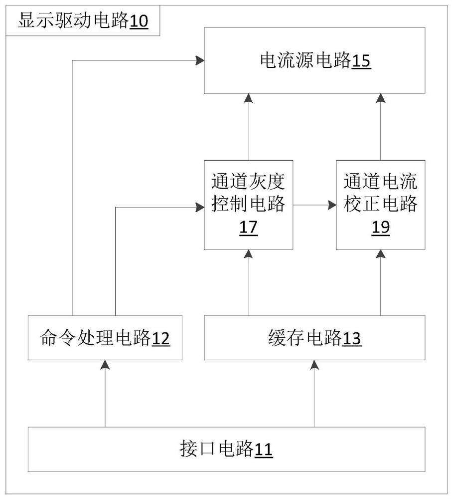
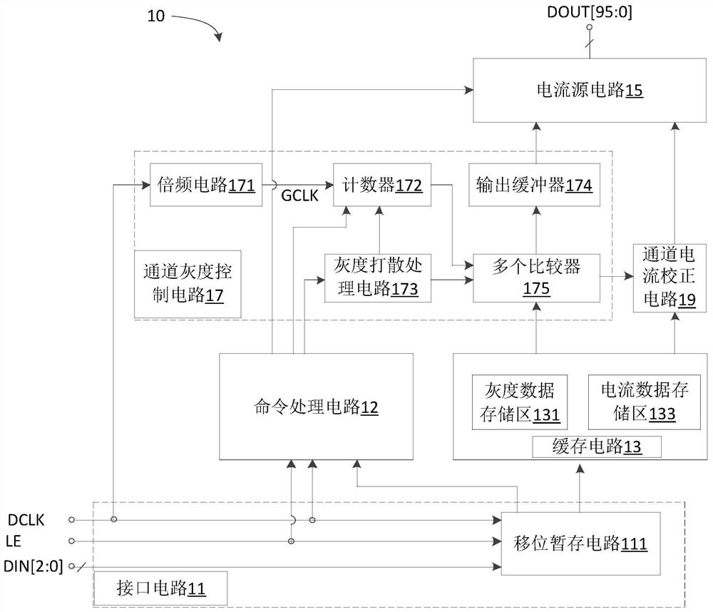
[0031] Figure 1A It is a schematic structural diagram of a display driving circuit 10 according to an embodiment of the present invention. The display driving circuit 10 can be used, for example, for a display panel such as an LED display panel, especially a packaged LED display panel on a board (COB (Chips On Board) packaged LED display panel). like Figure 1A As shown, the display driving circuit 10 includes: an interface circuit 11 , a command processing circuit 12 , a buffer circuit 13 , a current source circuit 15 , a channel grayscale control circuit 17 and a channel current correction circuit 19 .

[0032] The interface circuit 11 is used for receiving multiple grayscale data and multiple current data.

[0033] The command processing circuit 12 is electrically connected to the interface circuit 11, and includes, for example, a configuration register and circuit logic for responding to commands.

[0034] The buffer circuit 13 is electrically connected to the interface ...

no. 2 example

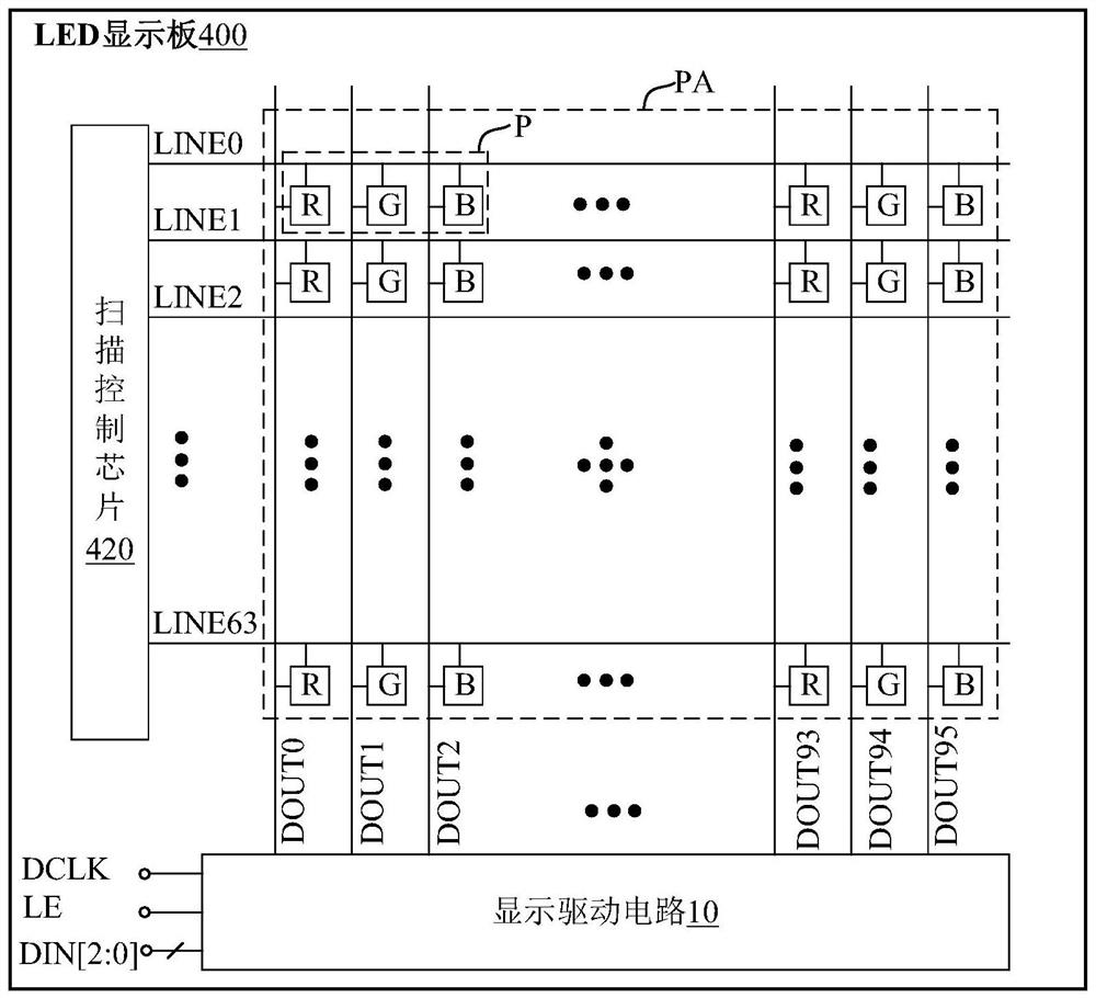
[0064] figure 2 This is a partial structural schematic diagram of an LED display panel provided by an embodiment of the present invention. like figure 2 As shown, the LED display panel 400 includes: a pixel array PA, a display driving circuit 10 and a scan control chip 420 .

[0065]The LED display panel 400 is, for example, a COB packaged LED display panel. For example, the chip-on-board (COB) integrated packaging technology directly encapsulates a plurality of LED chips on a metal-based printed circuit board, and directly dissipates heat through the substrate as a lighting module. The manufacturing process and cost of the bracket are reduced, and there is also the thermal benefit of reducing thermal resistance.

[0066] The pixel array PA includes 32 columns of pixels P, and each pixel P includes a plurality of different color LEDs such as R, G, B three primary color LED light points, so the pixel array PA has 96 columns of LED light points. The 96 columns of LED light ...

no. 3 example

[0070] image 3 This is a schematic structural diagram of a display device according to an embodiment of the present invention. like image 3 As shown, the display device 900 includes: a display control card 901 and an LED display panel 903 .

[0071] Wherein, the display control card 901 is used for outputting multiple grayscale data and multiple current data. For example, it adopts the hardware structure similar to the mature receiving card, scanning card or module controller in the field of LED display control technology, that is, using A programmable logic device such as an FPGA (Field Programmable Gate Array, Field Programmable Gate Array) device is used as an image processor; however, the image processor in this embodiment can directly output multiple grayscale data, multiple current data, or An FPGA device or an ASIC (Application Specific Integrated Circuit) device is added at the back end of the image processor to output multiple grayscale data and multiple current d...


PUM


Abstract

The embodiment of the invention discloses a display driving method and circuit, an LED display panel and a display device. The display driving method comprises the following steps: receiving and caching a plurality of pieces of gray data; acquiring a plurality of current data; determining multiple pieces of target current data in one-to-one correspondence with the multiple pieces of gray data in the multiple pieces of current data according to the multiple pieces of cached gray data; according to the plurality of pieces of gray data, respectively controlling the starting duration of the plurality of channel current sources; and respectively controlling the magnitude of the output current of the plurality of channel current sources according to the plurality of target current data. According to the embodiment of the invention, adaptive adjustment of the channel current can be realized, so that the problem of inconsistent light emitting wavelengths of an LED display panel, especially a COB packaged LED display panel, can be solved.

Description

technical field [0001] The present invention relates to the technical field of display control, and in particular, to a display driving method, a display driving circuit, an LED display panel and a display device. Background technique [0002] With the gradual maturity of small-pitch LED (Light Emitting Diode, light-emitting diode), users have higher and higher requirements for product stability and reliability, especially under the same conditions, requiring products to achieve better energy efficiency indicators, lower power consumption, and more competitive product prices. [0003] Compared with the traditional LED SMD package and high-power package, the chip-on-board (COB) integrated packaging technology directly encapsulates multiple LED chips on a metal-based printed circuit board, and directly dissipates heat through the printed circuit board as a lighting module. Not only can the manufacturing process of the bracket and its cost be reduced, but it also has the heat ...

Claims


Application Information

Patent Timeline
IPC IPC(8): G09G3/32
CPCG09G3/32
Inventor 韦科王伙荣
Owner XIAN TIBORS ELECTRONIC TECH CO LTD
Why Eureka
Try Eureka