Multi-range cross defrosting heat pump system and humidity control system

Inactive Publication Date: 2007-06-21
HU LUNG TAN
View PDF9 Cites 39 Cited by
  • Summary
  • Abstract
  • Description
  • Claims
  • Application Information

AI Technical Summary

Benefits of technology

[0010] 3. It is another object of the present invention to provide the most efficient defrosting control method for the multi-range cross defrosting heat pump system which is capable of defrosting with the heat energy absorbed from the environment and the heat energy generated from the co

Problems solved by technology

One of the reasons is the low efficiency of the heat pump under low working temperature, anot

Method used


Image

  • Multi-range cross defrosting heat pump system and humidity control system
  • Multi-range cross defrosting heat pump system and humidity control system
  • Multi-range cross defrosting heat pump system and humidity control system

Examples


Embodiment Construction

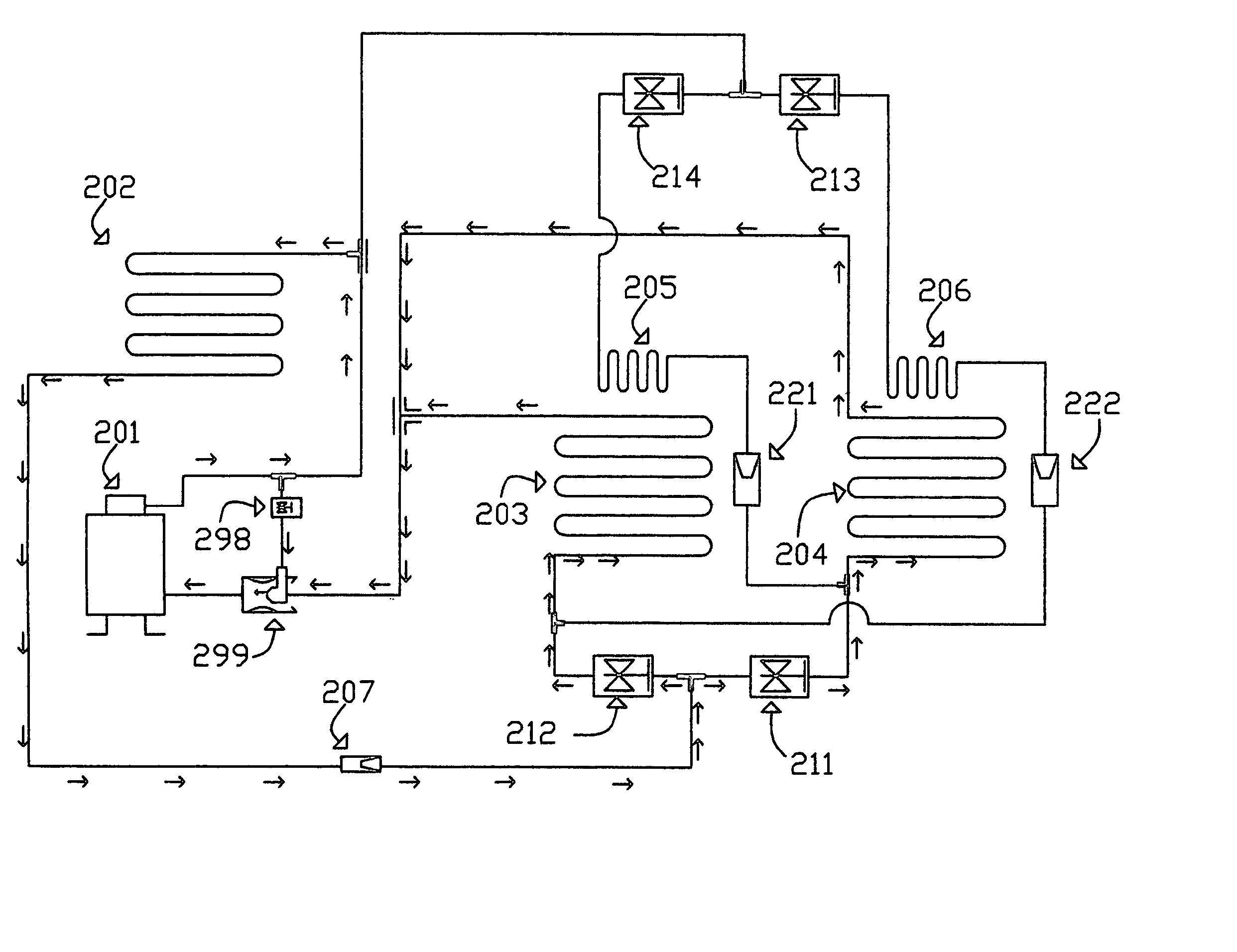
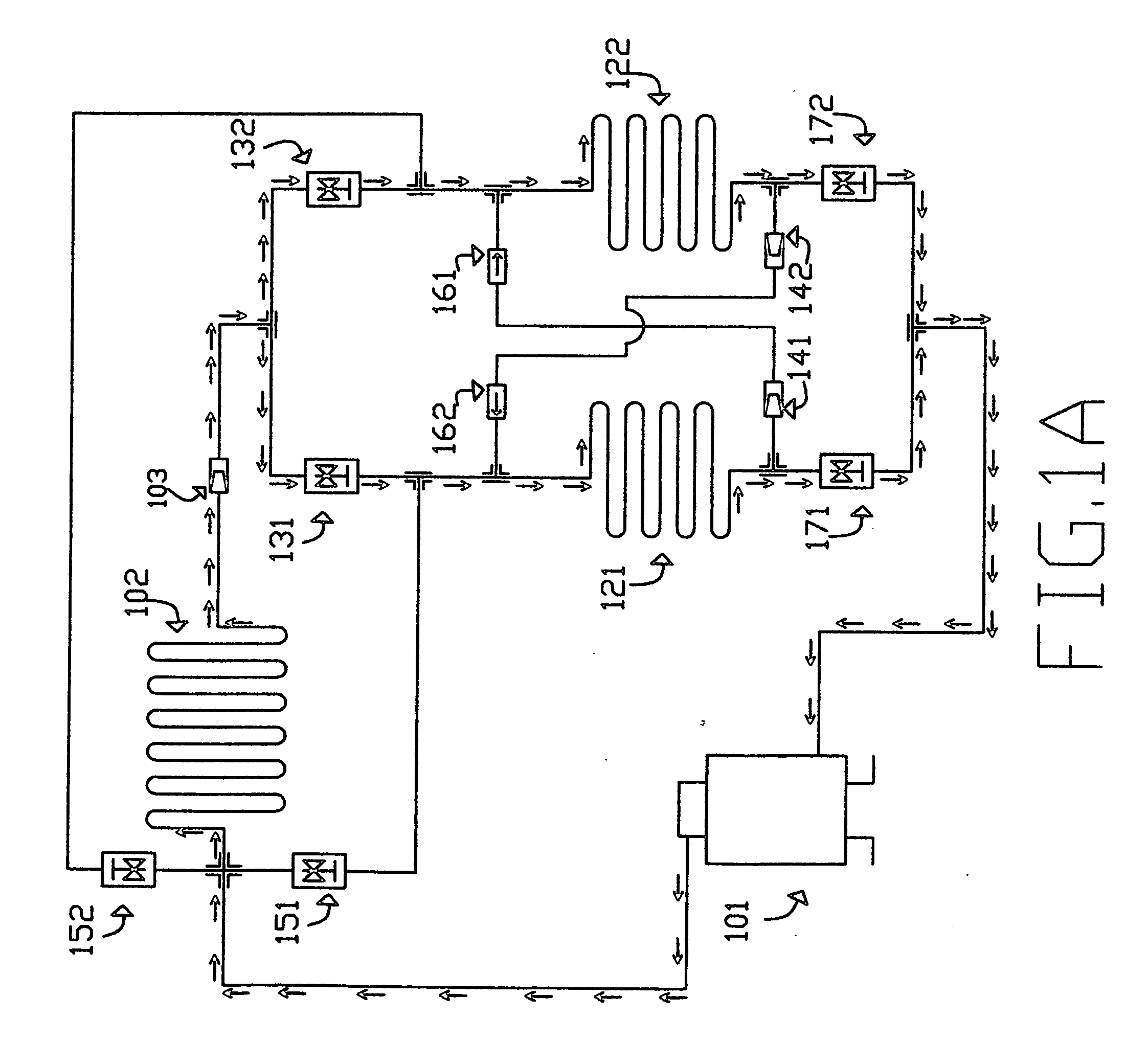
[0023] As shown in FIG. 1A, the cross reverse defrosting heat pump system comprising the following basic components: main compressor 101, main condenser 102, first evaporator 121, second evaporator 122, main expansion valve 103, first upper-flow control valve 131, second upper-flow control valve 132, first lower-flow control valve 171, second lower-flow control valve 172, first reverse-flow control valve 151, second reverse-flow control valve 152, first expansion valve 141, second expansion valve 142, first one-way valve 161, second one-way valve 162, first venting fan(not shown), second venting fan(not shown), separate insulation means(not shown) for each evaporator, and the logic control circuit(not shown).

[0024] When the outdoor temperature is above 12 degree Celsius, first evaporator 121 and second evaporator 122 should be capable of functioning without defrosting. When the outdoor temperature is between 5 to 12 degree Celsius, the logic control circuit employs first stage defr...


PUM


Abstract

The present invention provides an air-condition heat pump system and two-stage defrosting control method for continuous operation under an environment temperature range from 20 degree to negative 40 degree Celsius or lower. The heat pump system employs different defrosting methods under different temperature and humidity conditions. A ventilation and humidity control system is also provided for implementing the cross defrosting heat pump system within an indoor dimension.

Description

FIELD Field of the Invention [0001] The present invention relates to a multi-range air-condition heat pump, more particularly to a multi-range air-condition heat pump capable of uninterrupted operation. The present invention can be applied on residential, agriculture, commercial transportation, and industrial purposes. More particularly, the present invention can be used for air-conditioning, refrigeration. BACKGROUND OF THE INVENTION [0002] Current available heat pump requires different types of compressors for different range of working environment temperature, therefore, the user may need to install multiple air-conditioning systems such as a combination of a heat pump and a gas heater for different range of working temperature. One of the reasons is the low efficiency of the heat pump under low working temperature, another reason is the need for interrupting operation due to the frost conditions on evaporators. [0003] The current defrosting methods such as electrical defrost sys...

Claims


Application Information

Patent Timeline
IPC IPC(8): F25B47/00
CPCF25B5/02F25B29/003F25B47/022F25B2400/04F25B1/00F25B47/02F25B49/02
Inventor HU, LUNG TAN
Owner HU LUNG TAN
Why Eureka
Try Eureka