
Method and system for automatically calibrating sound level meter

a sound level meter and automatic calibration technology, applied in the direction of instruments, transmission monitoring, structural/machine measurement, etc., can solve the problems of high probability of incorrect adjustment, incorrect reading of sound pressure for calibration, and incorrect adjustmen

Inactive Publication Date: 2007-06-21
RION COMPANY
View PDF3 Cites 7 Cited by
  • Summary
  • Abstract
  • Description
  • Claims
  • Application Information

AI Technical Summary

Benefits of technology

The present invention provides a method, system, and apparatus for automatically calibrating a sound level meter using a sound calibrator. The sound calibrator generates a code signal based on sound, and the sound level meter switches into a calibration mode and automatically calibrates the sound level meter to adjust the value indicated by it to be a calibration sound pressure level of the code signal. The system may also output information about the sound calibrator, such as its type or manufacturing number, and the sound level meter may have a memory means to record calibration history. The technical effects of the invention include improved accuracy and efficiency in sound level measurement and calibration, and simplified and automated calibration procedures.

Problems solved by technology

Therefore, there is a likelihood that the sound pressure for calibration is incorrectly read or the adjustment is incorrectly performed.
More specifically, the likelihood of incorrect adjustment becomes high when the calibration is conducted in the measuring field.
In addition, even in the case of the same sound calibrator, since the transmission characteristic is different depending on the combination with the microphone of the sound level meter, it is not enough to simply correspond to the sound pressure of the sound calibrator, and thus correction in the sound level meter is needed.

Method used


Image

  • Method and system for automatically calibrating sound level meter
  • Method and system for automatically calibrating sound level meter
  • Method and system for automatically calibrating sound level meter

Examples


Embodiment Construction

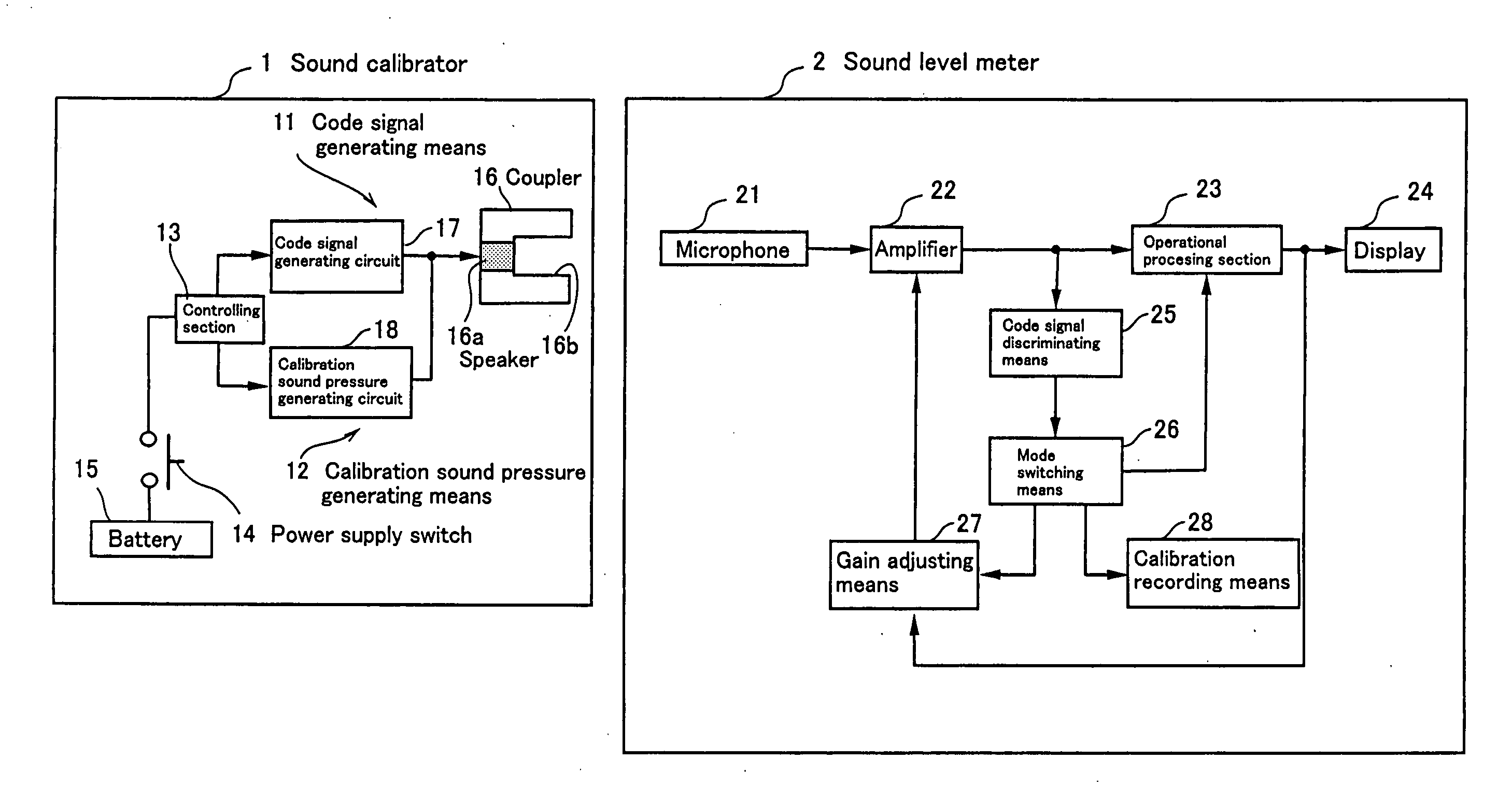
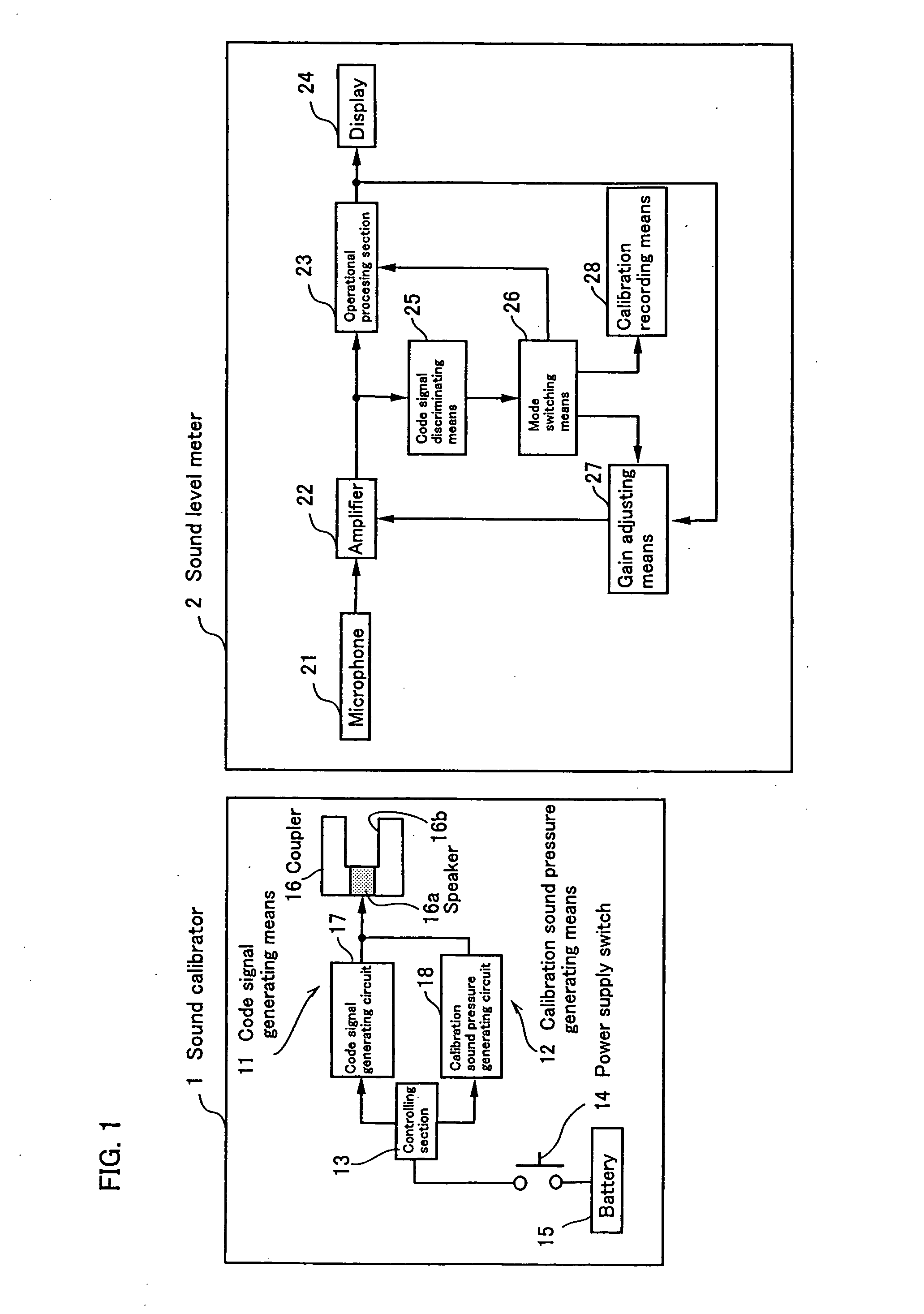
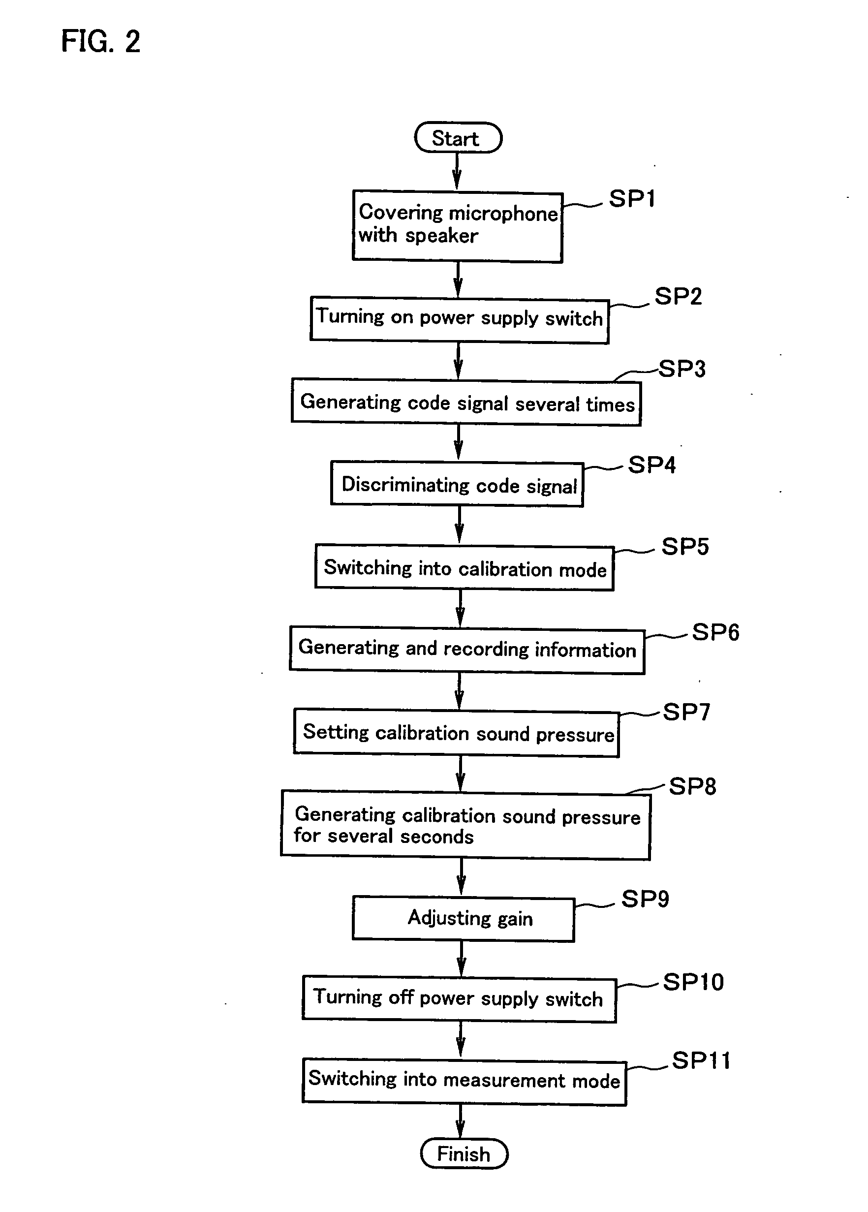
[0013] Hereinafter, embodiments according to the present invention will be explained with reference to the attached drawings. FIG. 1 is a block diagram of a system for automatically calibrating a sound level meter according to the present invention, and FIG. 2 is a flow chart of its operation sequence.

[0014] The system for automatically calibrating a sound level meter according to the present invention is comprised of a sound calibrator 1 and a sound level meter 2.

[0015] The sound calibrator 1 is comprised of a code signal generating means 11, a calibration sound pressure generating means 12, a controlling section 13, a power supply switch 14, and a battery 15.

[0016] The code signal generating means 11 is comprised of a coupler 16 provided with a speaker 16a and a code signal generating circuit 17, and generates a code signal (pulse signal) based on sound. The calibration sound pressure generating means 12 is comprised of the coupler 16 provided with the speaker 16a and a calibra...


PUM

PropertyMeasurementUnit
pressureaaaaaaaaaa
noise levelaaaaaaaaaa
atmospheric pressureaaaaaaaaaa

Abstract

A method and a system for automatically calibrating a sound level meter which achieves accurate and secure calibration of a sound level meter using a sound calibrator. The sound calibrator comprises a code signal generator and a calibration sound pressure generator. The sound level meter comprises a code signal discriminator, a mode switch for switching the mode into a calibration mode in response to the discrimination of the code signal discriminator, a gain adjuster for adjusting a gain of an amplifier such that the indicated value corresponds to the level of the calibration sound pressure in the calibration mode, and a calibration recorder for recording the calibration date and time, the sound pressure, the type, and the manufacturing number of the sound calibrator.

Description

TECHNICAL FIELD [0001] The present invention relates to a method and a system for automatically calibrating a sound level meter in which a sound level meter is automatically calibrated by using a sound calibrator. BACKGROUND ART [0002] When environmental noise is checked in accordance with regulations such as noise regulations, a precise noise level needs to be measured by using a sound level meter. In order to measure a precise noise level, a sound level meter must be periodically calibrated. For such calibration, predetermined accuracy is required in terms of legal regulations. [0003] Conventionally, when a sound level meter is calibrated by using a sound calibrator, the sound calibrator is connected to a microphone of the sound level meter, and the amplification magnitude of an amplifier circuit or the like is manually adjusted such that the sound level meter indicates a predetermined value with respect to the sound pressure generated by the sound calibrator. [0004] However, in t...

Claims


Application Information

Patent Timeline
Patent Type & Authority Applications(United States)
IPC IPC(8): G01N29/30G01H3/00
CPCG01H3/005
Inventor ICHIJO, KAZUO
Owner RION COMPANY
Learn More