Downhole measurement of formation characteristics while drilling

a technology of formation characteristics and downhole measurement, which is applied in the direction of borehole/well accessories, earth drilling and mining, etc., can solve the problems of inability to account for the diffusion of gas within the mud, the inability to accurately determine the depth of the well, and the inaccurate pump ra

Active Publication Date: 2007-06-21
SCHLUMBERGER TECH CORP
View PDF72 Cites 45 Cited by
  • Summary
  • Abstract
  • Description
  • Claims
  • Application Information

AI Technical Summary

Benefits of technology

[0023] The embodiments hereof are applicable to determination of various formation characteristics including, as non-limiting examples, one or more of the following: fluid content, fluid distribution, seal integrity, hydrocarbon maturity, fluid contacts, shale maturity, charge history, grain cementation, lithology, porosity, permeability, in situ fluid properties, isotopic ratios, trace elements in the solid, mineralogy, or type of clay.

Problems solved by technology

Recently, however, it has come back in favor; as operators have been able to extract valuable reservoir information that they have not been able to obtain by other relatively inexpensive methods.
Notwithstanding advances in equipment, techniques, and turnaround time for surface analysis of mud gas and cuttings, certain drawbacks remain.
One problem is depth control; that is, the ability to be able to accurately place the location of an acquired sample.
Given that pump rates are quite inaccurate and the mud properties vary significantly from surface to bottom hole, the depth determination is often unreliable.
Moreover, in general, no allowances are made for the diffusion of the gas within the mud or the inhomogeneity in the mixing as the mud travels along the well bore.
A further difficulty is that surface samples tend to be diluted with air and this has to be accounted for in the analysis.
Not only do the natural gas “reference samples” against which the extracted sample are compared have to be similarly diluted to obtain reliable results—this requires that the concentration of the mud gas be known a priori—but this dilution makes inaccurate or may even nullify the quantification of non-hydrocarbon gases such as nitrogen, helium and carbon dioxide.
This drawback involves, more generally, processes which alter the composition of the gas as it travels to surface and, when applicable, as it travels from wellsite to laboratory.
Also, one of the uncertainties that arises when performing mud-gas analysis at the surface is determining the true “background” level of the gas.
To somewhat improve on surface and laboratory analysis of mud gas and cuttings, there has been proposed, for example, downhole analysis for carbon dioxide gas, but with limited capability.

Method used


Image

  • Downhole measurement of formation characteristics while drilling
  • Downhole measurement of formation characteristics while drilling
  • Downhole measurement of formation characteristics while drilling

Examples


Embodiment Construction

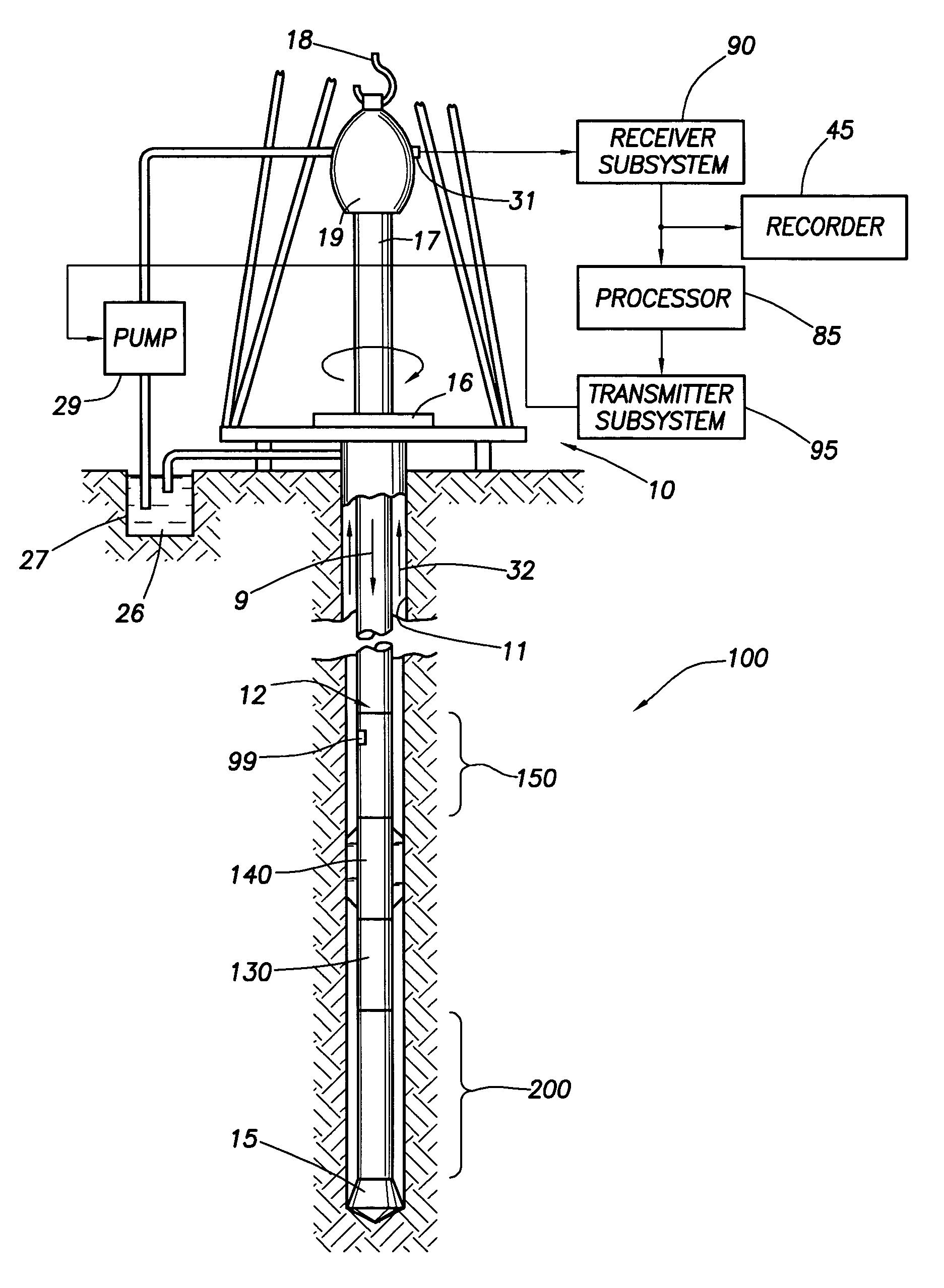
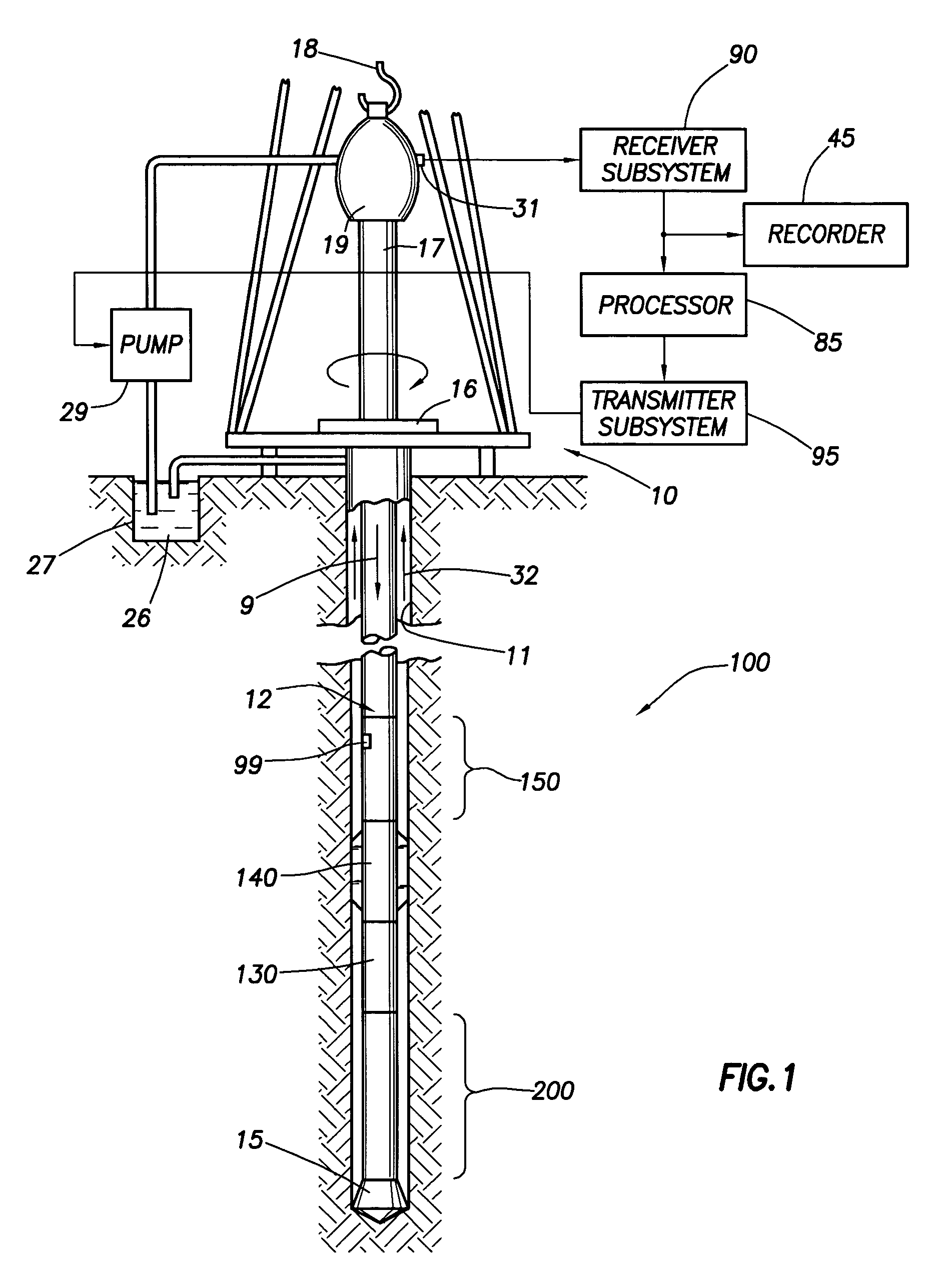
[0037] Referring to FIG. 1, there is illustrated a measuring-while-drilling apparatus which can be used in practicing embodiments of the invention. [As used herein, and unless otherwise specified, measurement-while-drilling (also called measuring-while-drilling or logging-while-drilling) is intended to include the taking of measurements in an earth borehole, with the drill bit and at least some of the drill string in the borehole, during drilling, pausing, sliding and / or tripping.]

[0038] A platform and derrick 10 are positioned over a borehole 11 that is formed in the earth by rotary drilling. A drill string 12 is suspended within the borehole and includes a drill bit 15 at its lower end. The drill string 12 and the drill bit 15 attached thereto are rotated by a rotating table 16 (energized by means not shown) which engages a kelly 17 at the upper end of the drill string. The drill string is suspended from a hook 18 attached to a traveling block (not shown). The kelly is connected t...


PUM


Abstract

A method for determining a property of formations surrounding an earth borehole being drilled with a drill bit at the end of a drill string, using drilling fluid that flows downward through the drill string, exits through the drill bit, and returns toward the earth's surface in the annulus between the drill string and the periphery of the borehole, including the following steps: obtaining, downhole near the drill bit, a pre-bit sample of the mud in the drill string as it approaches the drill bit; obtaining, downhole near the drill bit, a post-bit sample of the mud in the annulus, entrained with drilled earth formation, after its egression from the drill bit; implementing pre-bit measurements on the pre-bit sample; implementing post-bit measurements on the post-bit sample; and determining a property of the formations from the post-bit measurements and the pre-bit measurements.

Description

FIELD OF THE INVENTION [0001] This invention relates to the field of determination of characteristics of formation surrounding an earth borehole and, more particularly, to the determination, using downhole measurements, of such characteristics during the drilling process. BACKGROUND OF THE INVENTION [0002] Prior to the introduction of Logging While Drilling (LWD) tools and measurements, analysis of cuttings and mud-gas logging were the primary formation evaluation techniques used during drilling. With the advent of LWD, mud-gas logging lost some of its luster and was viewed as a “low technology” discipline. Recently, however, it has come back in favor; as operators have been able to extract valuable reservoir information that they have not been able to obtain by other relatively inexpensive methods. [0003] The present-day approach to mud-gas logging is fundamentally the same as it has traditionally been: extract and capture a surface sample of gas or hydrocarbon liquid vapor from th...

Claims


Application Information

Patent Timeline
Patent Type & Authority Applications(United States)
IPC IPC(8): E21B49/08
CPCE21B49/005E21B49/081
Inventor POP, JULIANTAHERIAN, REZAPOITZSCH, MARTIN E.TABANOU, JACQUES R.
Owner SCHLUMBERGER TECH CORP
Why Eureka
Try Eureka