Rotary leadthrough of a robot arm

Inactive Publication Date: 2007-06-21
ROBERT BOSCH GMBH
View PDF8 Cites 12 Cited by
  • Summary
  • Abstract
  • Description
  • Claims
  • Application Information

AI Technical Summary

Benefits of technology

[0005] It is therefore an object of the invention to create a rotary leadthrough for a robot arm, in particular for a fourth

Problems solved by technology

Cleaning the rotary leadthrough of the four

Method used


Image

  • Rotary leadthrough of a robot arm
  • Rotary leadthrough of a robot arm
  • Rotary leadthrough of a robot arm

Examples


Embodiment Construction

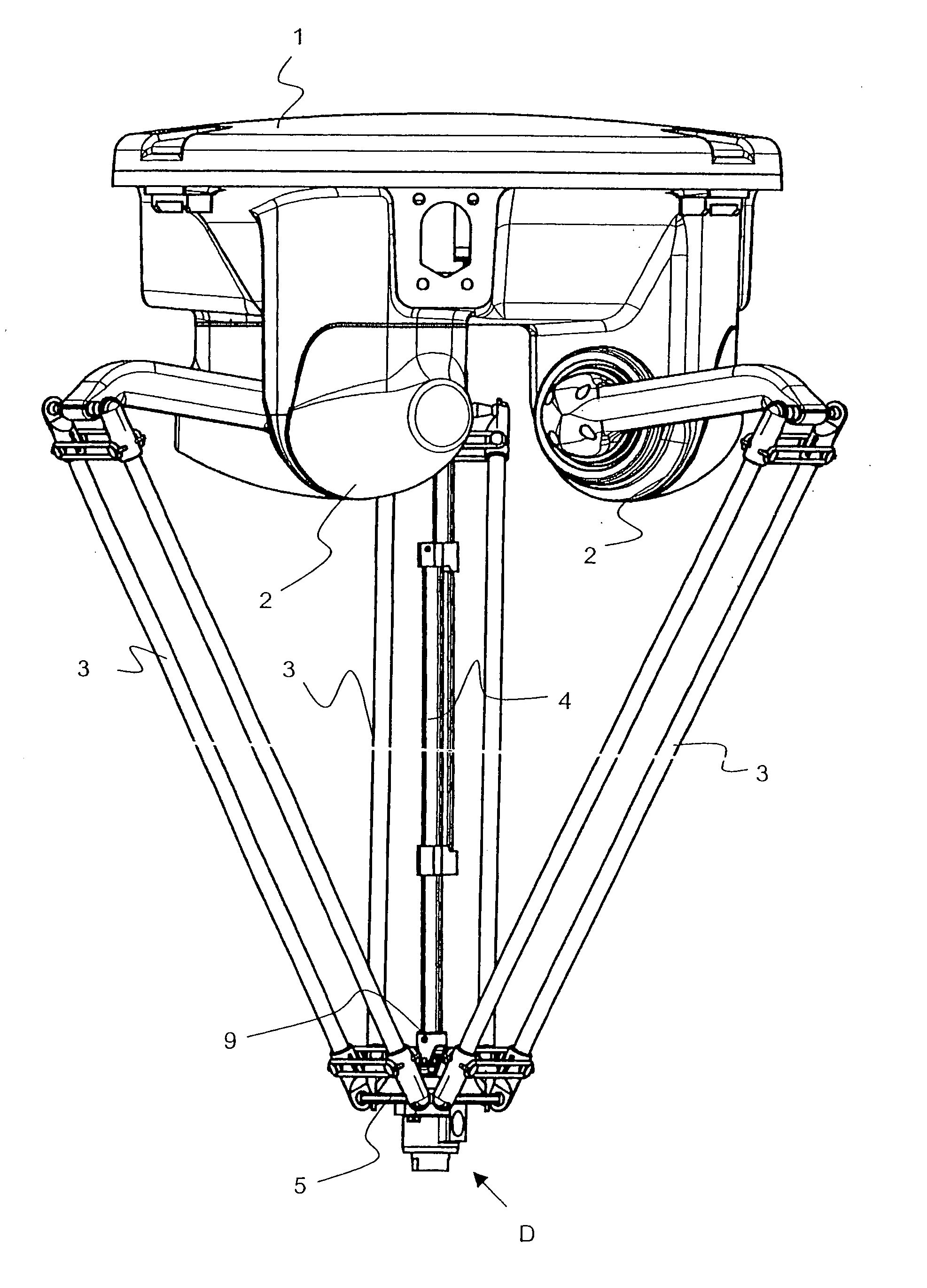
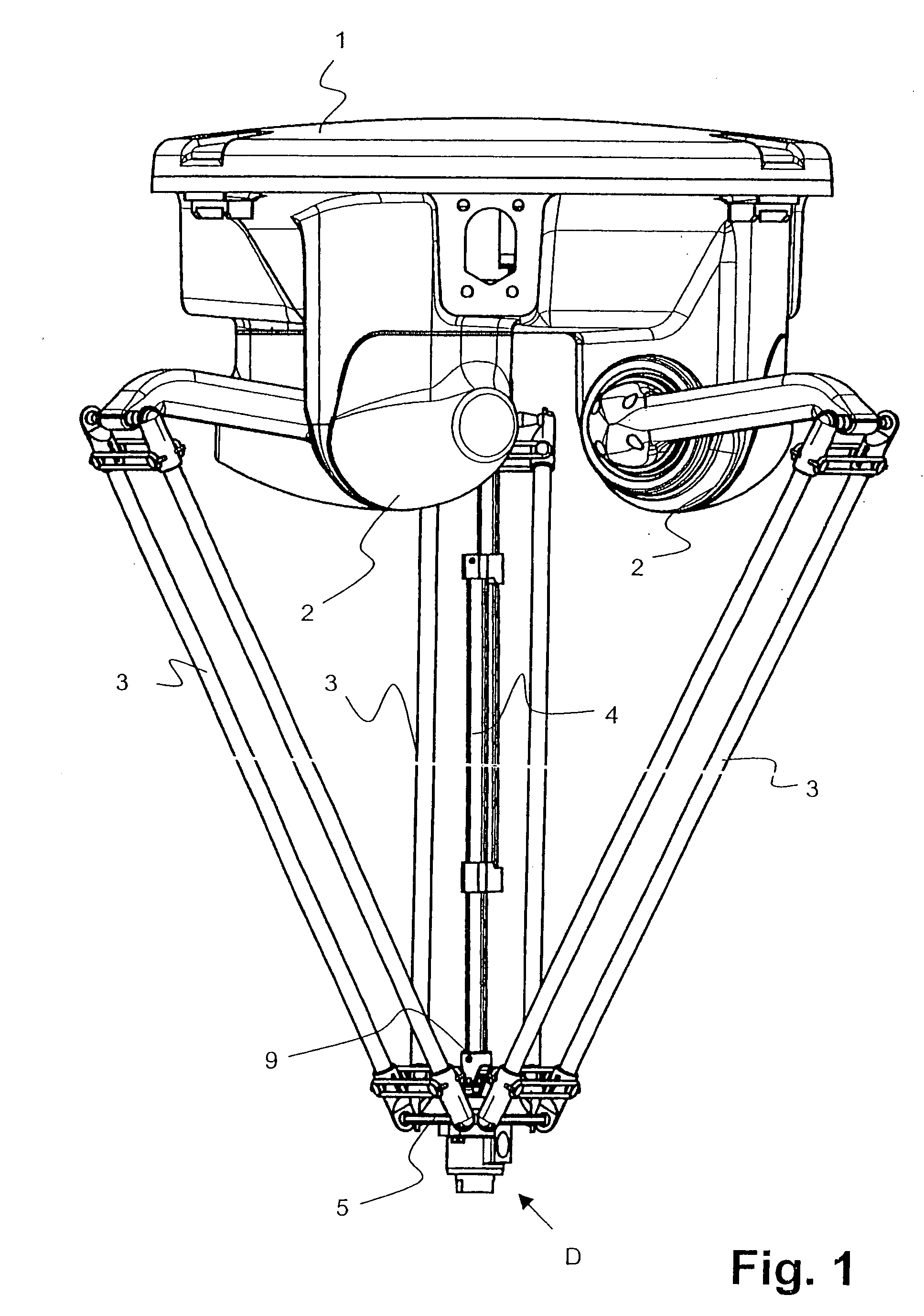
[0019] In FIG. 1, a Delta robot is shown. Except for the rotary leadthrough D described hereinafter, it is equivalent to the known Delta robots and will therefore be described only briefly below.

[0020] It has a platelike basic element 1, on which three control arms 3 are supported so as to be pivotable or rotatable. The three control arms 3 can be moved individually by means of motors 2. The free ends of the control arms 3 are pivotably connected to a carrier element, in this case a carrier plate 5. The Delta robot also has a fourth axle 4, which is often telescoping or otherwise changeable in length. This fourth axle 4 is connected to the rotary leadthrough D via a joint 9, in particular a cardan joint or a universal joint. A grasping element, not shown, can be secured to the rotary leadthrough D on the side of the rotary leadthrough D diametrically opposite the fourth axle 4. The type of grasping element depends on the field in which it to be used. Examples of grasping elements a...


PUM


Abstract

A rotary leadthrough of a robot arm, in particular of a fourth axle of a Delta robot, has a housing and a shaft, located in an axial leadthrough of the housing and supported rotatably in this housing, for connection to the robot arm. The housing has at least two openings for cleaning the axial leadthrough. The shaft at least in a portion of its length, has a diameter which is less than the diameter of the axial leadthrough in that region, so that there is a void between the shaft and the axial leadthrough.

Description

FIELD OF THE INVENTION [0001] The invention relates to a rotary leadthrough of a robot arm, in particular of a fourth axle of a Delta robot, as generically defined by the preamble to claim 1. PRIOR ART [0002] Delta robots are known from European Patent Disclosures EP-B 0 250 470, EP-A 1 129 829, and EP-A 1 293 691. These Delta robots are suitable for moving objects precisely and in a guided way in three-dimensional space. They have proven themselves in practice and are used, among other fields, in the food industry or in machining centers that have stringent cleanliness requirements. Cleaning the rotary leadthrough of the fourth axle, however, is sometimes complicated. Until now, this rotary leadthrough has been embodied such that a hollow shaft was supported in a housing, and the shaft had a radial inflation opening in its central void. [0003] Precisely in the aforementioned areas of use, however, it would be desirable to be able to clean the entire robot and especially the region ...

Claims


Application Information

Patent Timeline
IPC IPC(8): B25J17/02
CPCB25J17/0266Y10T74/20335B25J9/0051B25J17/02B25J18/00
Inventor SCHULER, SAMUELFILIPPI, MARTINO
Owner ROBERT BOSCH GMBH
Why Eureka
Try Eureka