Trash rack for nuclear power plant

a technology for nuclear power plants and trash racks, which is applied in the direction of nuclear elements, greenhouse gas reduction, separation processes, etc., can solve the problems of large strainer heads, large strainer designs, and reduced strainer design. , to achieve the effect of safe pressure head

Inactive Publication Date: 2007-06-21
CONTINUUM DYNAMICS
View PDF18 Cites 7 Cited by
  • Summary
  • Abstract
  • Description
  • Claims
  • Application Information

AI Technical Summary

Benefits of technology

[0011] It is an object of the present invention to provide an improved trash rack that can trap

Problems solved by technology

A LOCA can involve failure of reactor components that introduce large quantities of solid matter into the cooling water, which entrains the solids and carries them back to the suppression pool.
In other words, in both types of reactor, cooling water is drawn from a reservoir and pumped to the reactor core, and entrained solids can impair cooling and damage the ECCS pumps if permitted to circulate with the water.
There has been considerable effort expended on strainer design to decrease head loss across the strainer for the intended coolant flow.
However, increasing strainer surface area makes the strainer larger, and thus more expensive and more difficult to work with.
Moreover, if strainers are subjected to too much debris, they will begin to clog even if

Method used


Image

  • Trash rack for nuclear power plant
  • Trash rack for nuclear power plant
  • Trash rack for nuclear power plant

Examples


Embodiment Construction

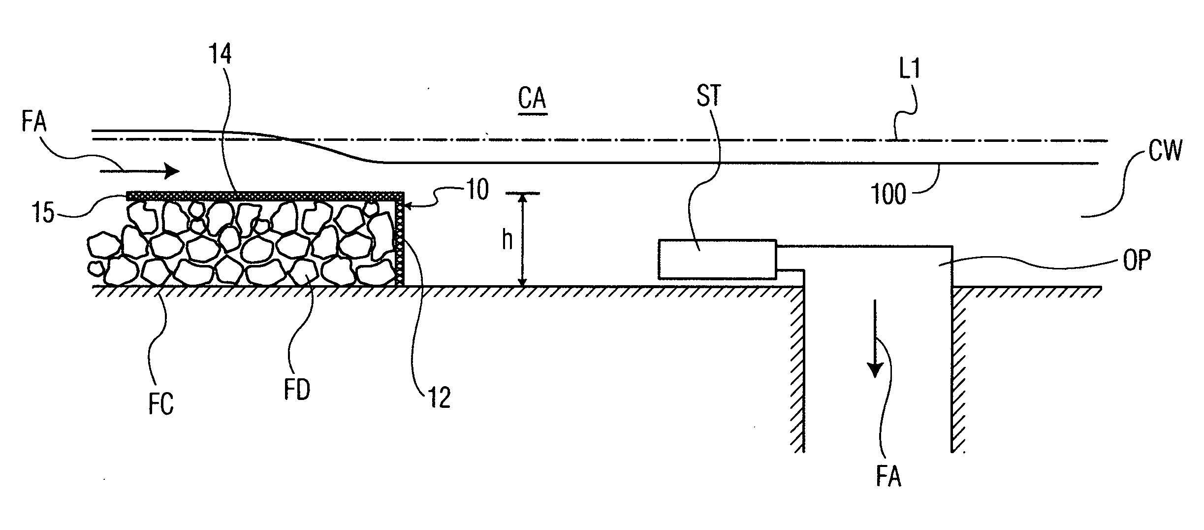
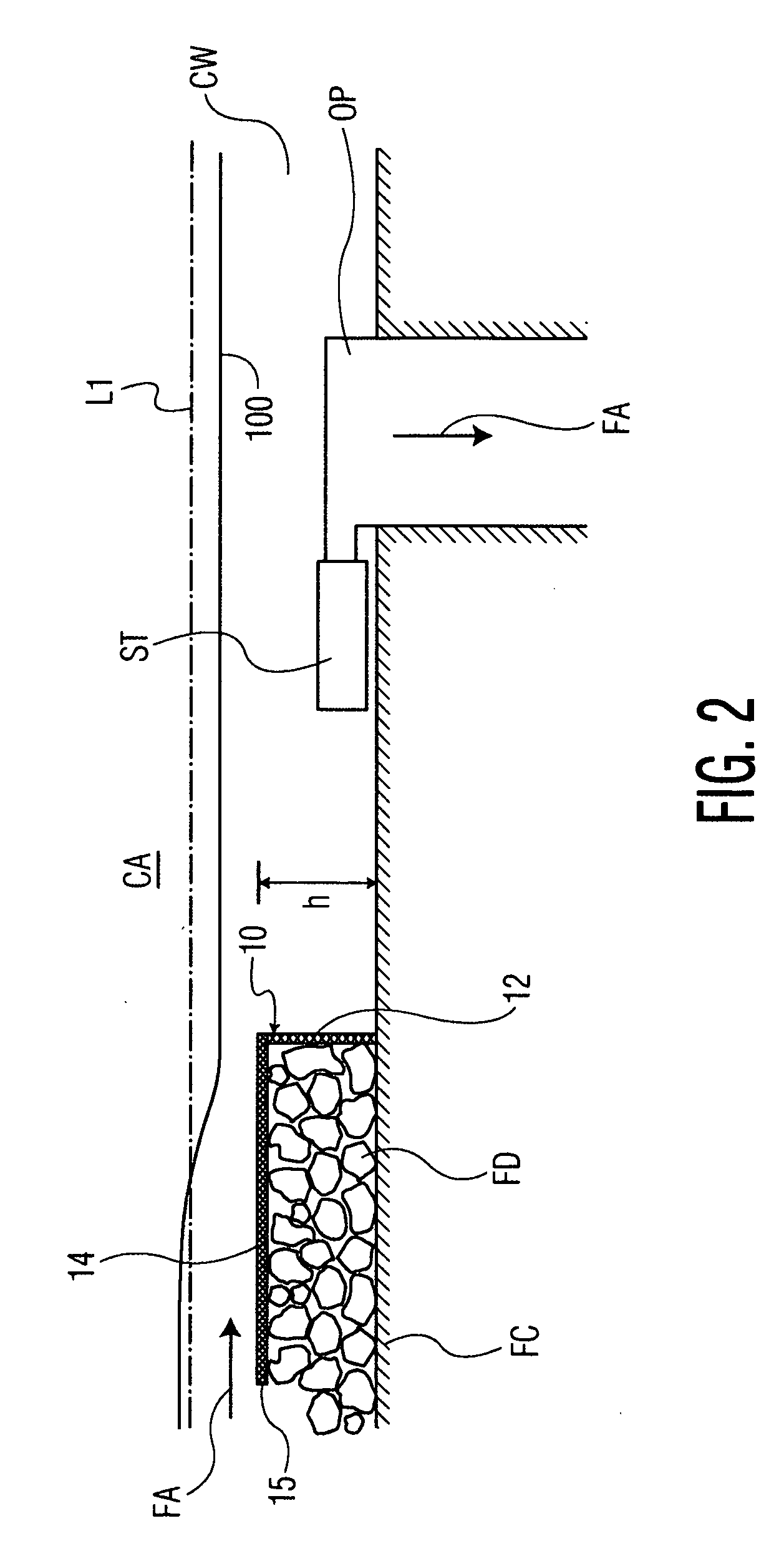
[0028]FIG. 2 schematically illustrates a trash rack 10 in accordance with a basic embodiment of the present invention installed in a reactor containment area CA in a fashion similar to that shown in FIG. 1, namely so that coolant flow FA passes through the trash rack 10 before it reaches the strainer ST and the outlet pipe OP. The trash rack 10 includes a generally upright panel member 12 that in this embodiment is a heavy wire-mesh sheet (woven in a manner similar to a window screen) that is strong enough to withstand the hydrodynamic forces exerted by the coolant flow when the member 12 becomes partially or wholly blocked by the debris FD. The panel member 12 is generally planar and is secured in place perpendicular to the floor FC with its bottom edge in mating contact with the floor.

[0029] In addition, the trash rack 10 includes a generally planar roof panel member 14 that in the present embodiment is also a wire-mesh sheet. The downstream edge of the roof member 14 is disposed...


PUM

PropertyMeasurementUnit
Angleaaaaaaaaaa
Cell angleaaaaaaaaaa

Abstract

A trash rack for an emergency core cooling system of a nuclear power plant comprises at least one wire-mesh upright screen for filtering debris from coolant flowing in the cooling system. The upright screen is mounted in the coolant flow path with its bottom edge on the floor of an area forming part of the cooling system and a top edge is disposed above the floor at a height less than the level to which the coolant can be expected to rise during a loss of cooling accident. The trash rack also uniquely includes a wire-mesh roof screen that has a downstream edge mated with the top edge of the upright screen and extending upstream thereof to an upstream end spaced from the floor, thereby presenting an unobstructed opening between the floor and the upstream edge of the roof screen.

Description

CROSS-REFERENCE TO RELATED APPLICATIONS [0001] This application claims the benefit of U.S. provisional application No. 60 / 732,122, filed Nov. 2, 2005, the contents of which are incorporated herein by reference.BACKGROUND OF THE INVENTION [0002] 1. Field of the Invention [0003] The present invention relates to a trash rack for a water-cooled nuclear power plant, and more particularly, to a trash rack capable of intercepting significant amounts of debris in a reactor coolant flow while maintaining a sufficient coolant flow rate. [0004] 2. Description of Related Art [0005] A nuclear power plant typically includes an emergency core cooling system (ECCS) that circulates large quantities of cooling water to critical reactor areas in the event of accidents. A boiling water reactor (BWR) commonly draws water from one or more reservoirs, known as suppression pools, in the event of a loss of coolant accident (LOCA). Water is pumped from the suppression pool to the reactor core and then circul...

Claims


Application Information

Patent Timeline
IPC IPC(8): B01D29/00B01D33/00
CPCB01D24/008E02B5/085G21C9/016G21Y2002/207G21Y2002/301G21Y2002/304G21Y2004/30Y02E30/40Y02E30/30
Inventor BILANNIN, ALAN J.
Owner CONTINUUM DYNAMICS
Why Eureka
Try Eureka