Method for operating an injection molding machine

Inactive Publication Date: 2007-06-21
KRAUSS MAFFEI KUMSTSTOFFTECHNIK GMBH
View PDF2 Cites 2 Cited by
  • Summary
  • Abstract
  • Description
  • Claims
  • Application Information

AI Technical Summary

Benefits of technology

[0013] With the method of the invention, short-term force peaks, which may be encountered, e.g., as a result of vibrations in the foundation caused by adjacent machines, can advantageously be filtered out, without causing the drives and hence of the injection molding machine to be inadvertently switched off. Another advantage is that the tolerated force region can be selected to be relatively small, without the risk of damaging a molding tool.
[0014] According to another feature of the present invention, the travel path can be divided into a plurality of zones, wherein the tolerance clamping force may be constant within a zone. The zones can be relatively small, which lessens the risk of damaging a molding tool.
[0015] According to another feature of the present invention, tool wear can be detected early by evaluating the actual force curve and by evaluating the time durations during which the maximum force is exceeded. This can prevent damage to a molding tool by performing maintenance works before the damage actually occurs.
[0016] According to another feature of the present invention, the maximum or minimum travel force may act on the mold halves only for a short time, thereby minimizing possible damage to the molding tool or the molded part. In addition, the tolerance clamping force can advantageously be defined either as a fixed value or as a percentage of a desired clamping force applied during an opening and / or closing movement of the mold half along the travel path of the mold half. This value or percentage can be selected to be quite small, thereby also minimizing possible damage to the molding tool or the molded part.

Problems solved by technology

However, with more complicated molding tool designs, for example with an injection molding tool having a plurality of sliders that must be closed when a mold is closed, this method does not always provide the required accuracy.
Triggering can be faulty, for example as a result of vibrations of the foundation or shocks in the hydraulic system.
More complex molds with one or more sliders do not have a constant closing operation with respect to acceleration.
The method disclosed in EP 0158031 may therefore produce unwanted false alarms, causing interruption of the closing movement of the mold and hence the operation of the injection molding machine.
This method has the disadvantage that it can be easily manipulated by an operator.
Such improper manipulation is undesirable.

Method used


Image

  • Method for operating an injection molding machine

Examples


Embodiment Construction

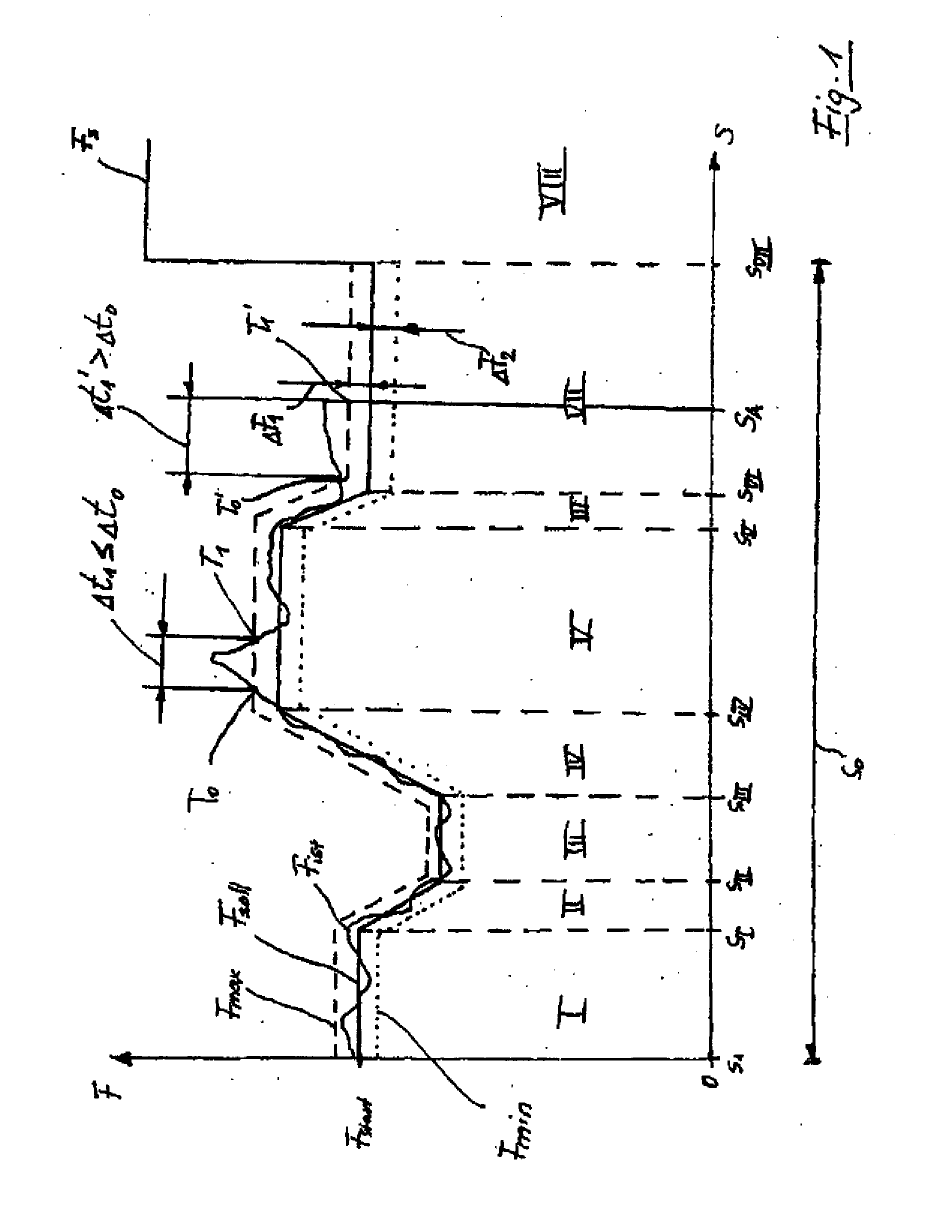
[0018] The depicted embodiment is to be understood as illustrative of the invention and not as limiting in any way. It should also be understood that the drawings are not necessarily to scale and that the embodiments are sometimes illustrated by graphic symbols, phantom lines, diagrammatic representations and fragmentary views. In certain instances, details which are not necessary for an understanding of the present invention or which render other details difficult to perceive may have been omitted.

[0019]FIG. 1 shows schematically a force pattern along a closing path So of a mold half. The closing path So is divided in the example of FIG. 1 into zones I to VII. A solid line consisting, for example, of straight line segments represents a desired clamping force Fsoll and its course along a closing path S0.

[0020] A broken line which extends parallel to and is, in particular offset from the solid line of the desired clamping force Fsoll, represents a maximum allowable clamping force F...


PUM

PropertyMeasurementUnit
Timeaaaaaaaaaa
Timeaaaaaaaaaa
Forceaaaaaaaaaa

Abstract

In a method for operating an injection molding machine an actual clamping force is measured during an opening and / or closing movement of a mold half along a travel path. A force pattern of a maximum allowable clamping force and / or a minimum allowable clamping force is predefined along the travel path, and the measured actual clamping force is compared with the maximum and / or minimum clamping forces, respectively. When the actual clamping force surpasses the maximum clamping force or falls short of the minimum clamping force, a time measurement is started, wherein a drive of the mold half is switched off, when the time measurement exceeds a predetermined time duration.

Description

CROSS-REFERENCES TO RELATED APPLICATIONS [0001] This application is a continuation of prior filed copending PCT International application no. PCT / EP2005 / 009029, filed Aug. 20, 2005, which designated the United States and has been published but not in English as International Publication No. WO 2006 / 027100 and on which priority is claimed under 35 U.S.C. §120, and which claims the priority of German Patent Application, Serial No. 10 2004 043 300.3, filed Sep. 8, 2004, pursuant to 35 U.S.C. 119(a)-(d), the contents of which are incorporated herein by reference in its entirety as if fully set forth herein. BACKGROUND OF THE INVENTION [0002] The present invention is directed, in general, to a method for operating an injection molding machine. More particularly, the present invention is directed to a method for triggering a tool safety device when the mold opening / closing forces exceed or fall short of specified values for the mold opening / closing forces along the travel path of the mova...

Claims


Application Information

Patent Timeline
IPC IPC(8): B29C45/76
CPCB29C45/76B29C45/844
Inventor GRIMM, GUNTHER
Owner KRAUSS MAFFEI KUMSTSTOFFTECHNIK GMBH
Why Eureka
Try Eureka