Driving element and saddle chain

a technology of driving element and saddle chain, which is applied in the direction of thin material handling, sheet binding, article delivery, etc., can solve the problems of inability to achieve, and achieve the effect of easy, quick and low-damage method of changing the chain pitch, and increasing the productivity of saddle stitchers

Inactive Publication Date: 2009-04-21
MULLER MARTINI HLDG
View PDF5 Cites 0 Cited by
  • Summary
  • Abstract
  • Description
  • Claims
  • Application Information

AI Technical Summary

Benefits of technology

[0007]To solve the problems described above, preferred embodiments of the present invention provide driver elements and a corresponding saddle chain which enable a quick, easy, and low-damage method of changing the chain pitch, and thereby increasing the productivity of a saddle stitcher having such a saddle chain with corresponding driver elements.
[0008]According to a preferred embodiment, drivers include a driver element for an endless saddle chain in a saddle line. The saddle chain includes saddle segments and receiver segments, wherein the saddle segments have a substantially saddle-shaped roof of the saddle chain and the driver element is detachably fastened without tools to a respective receiver segment. The driver element includes two driving flaps, with the driving flaps being pre-tensioned against each other. The pre-tensioning between the driving flaps provides a snap action, resulting in secure and reproducible locking of the driver element in the receiver segment. In this manner, the installing and removing of the driver elements from the saddle chain to change its pitch is performed without the use of tools. Due to this, the refitting time for different chain pitches is drastically reduced and, thus, the productivity is increased. Furthermore, such a toolless refitting is typically rather easy and can be performed by a less talented operator quickly, easily, and without the risk of damaging the device.
[0010]In another preferred embodiment of the driver element, the driving flaps have a common swivel axis, and, in the installed position in the saddle chain, the driving flaps are tensioned against the inner sides of the saddle chain. Furthermore, the driving flaps include an extension that extends the interior of the roof of the saddle chain, and a connection element provided on the extension, with which the driver elements can be detachably connected to the saddle chain. Thus, the driver elements can be easily pressed together at the flaps for inserting into the saddle chain. Due to the common swivel axis, the extension of the flaps extending inside the roof is compressed, e.g., against a spring in a similar to scissors. If the compressed driver element is then relieved of tension in the position inside the roof of the saddle chain, the spring pre-tensions the extensions of the flaps against the inside of the saddle chain. Advantageously, corresponding detent bolts or similar detachable fasteners are engaged at these positions, so that the driver element is securely installed in the saddle chain. A removal of the driver element from the saddle chain is performed by simply pressing the driver flaps together, whereby the locking is released. The corresponding detent elements can either be a portion of the receiver segments provided on the saddle chain or a portion of the driver elements, or a combination of both, as is generally known from the prior art for such detent systems. Furthermore, a clamping mechanism may be used as an alternative to a spring, whether active or passive, such as various other elastic materials. Advantageously, however, these elements are especially simple and user-friendly, low-maintenance, and economical, such as the aforementioned spring, for example.
[0012]In another preferred embodiment of the endless saddle chain, a cover element on at least one receiver segment is fastened and removed without the use of tools, and the cover element is substantially flush with the saddle-shaped roof of the saddle chain. This enables completely covering the saddle chain for different chain pitches in order to reduce the danger of injury and to avoid dirtying the signatures and the saddle chain. Preferably, all receiver segments in which no driver element is installed are covered with such a cover element. The cover piece can be an injection molded component, which can move in the nature of a hinge, i.e., the cover piece has a desired elasticity.

Problems solved by technology

Advantageously, the drivers can directly push the signatures from the bearing blade, which is not possible when the drivers are arranged directly on the ridge of the saddle chain.

Method used


Image

  • Driving element and saddle chain
  • Driving element and saddle chain
  • Driving element and saddle chain

Examples


Embodiment Construction

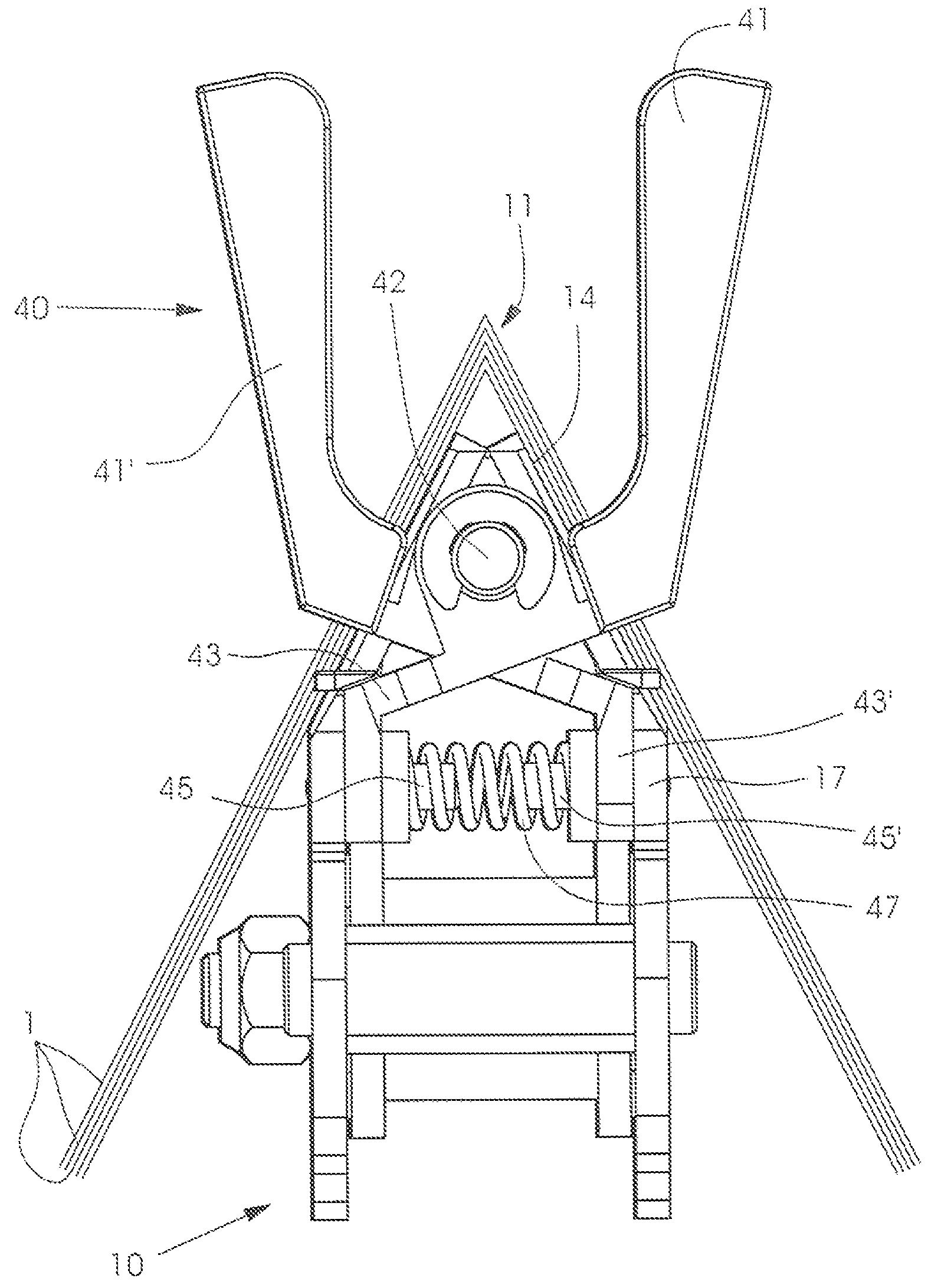
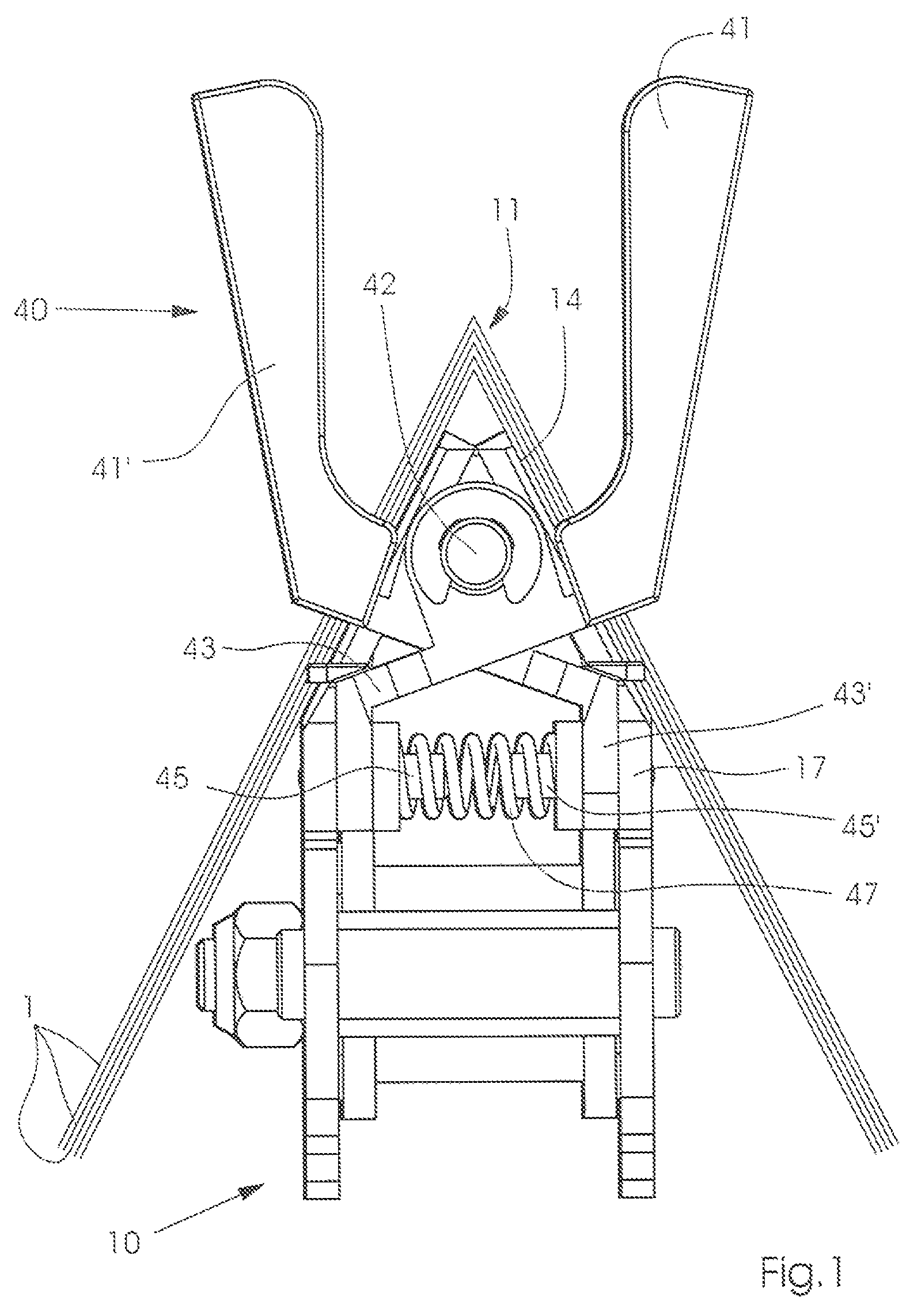
[0017]The endless saddle chain 10 and the driver elements according to a preferred embodiment of the present invention, shown in FIGS. 1 to 3, are shown schematically. Additional elements necessary for the operation, such as bearings, drive units, controls, and other elements, which are not relevant to the present invention, are shown only schematically or not at all, since they are known and would hamper an understanding of the present invention.

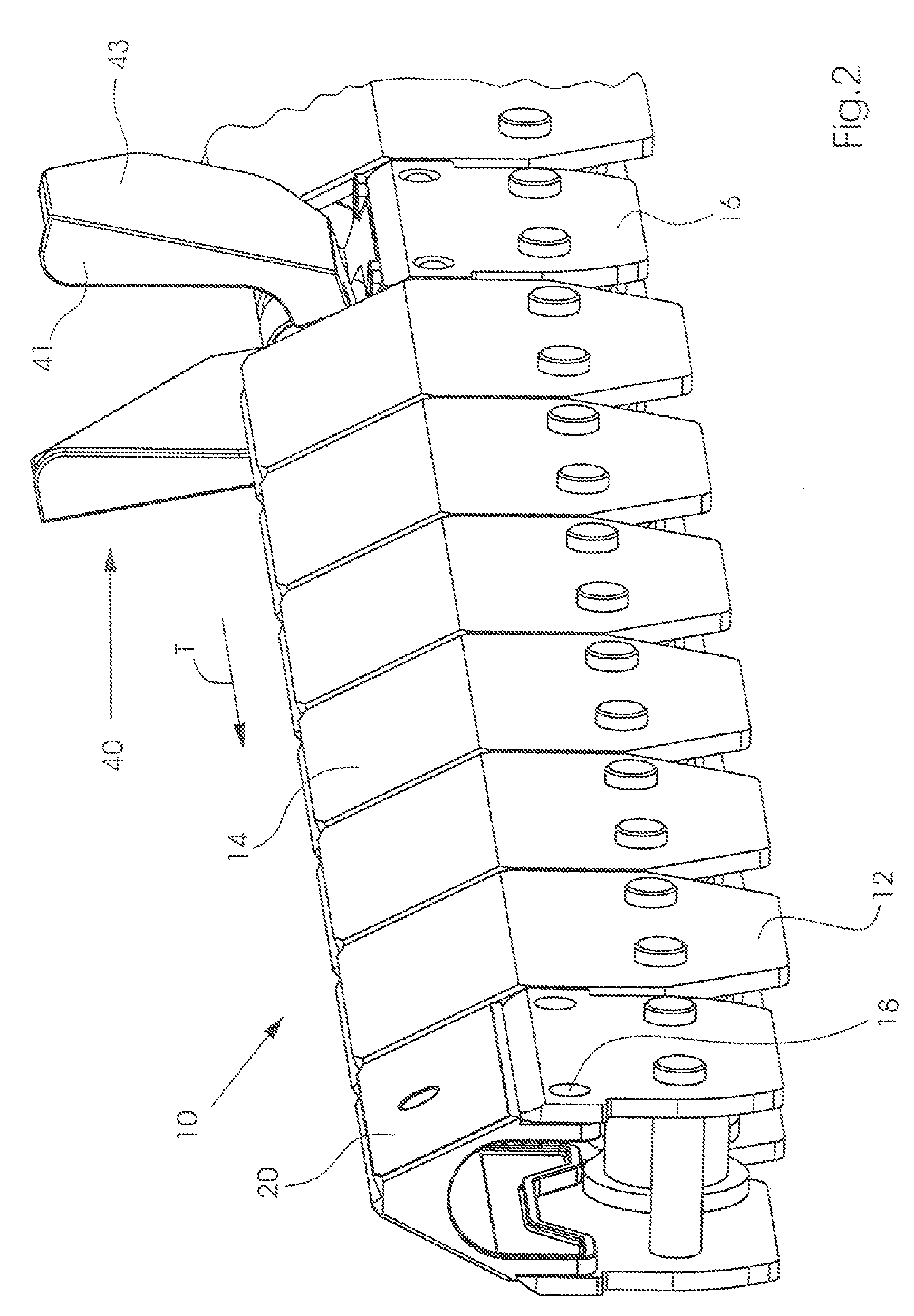
[0018]An endless saddle chain 10, which can be used in a saddle stitcher of the prior art (not shown), includes saddle segments 12 and receiver segments 16. Chain segments are disposed between the saddle segments 12 and the receiver segments 16, which are conventional for saddle chains of this kind. The number of chain piece 30 of the endless saddle chain 10 depends primarily on the number of feeders, which place signatures 1 on the saddle chain 10.

[0019]As shown in FIG. 3, the saddle chain 10 includes identical chain pieces 30 of a length ...


PUM


Abstract

A driver element is provided for an endless saddle chain in a saddle line, wherein the saddle chain includes saddle segments and receiver segments, with the saddle segments defining a substantially saddle-shaped roof of the saddle chain. The driver element is arranged to be detachably fastened without tools to a respective one of the receiver segments. The driver element includes two driving flaps that are pre-tensioned against each other.

Description

BACKGROUND OF THE INVENTION[0001]1. Field of the Invention[0002]The invention relates to a driving element for an endless saddle chain, especially in the processing of printed matter, and a corresponding endless saddle chain.[0003]2. Description of the Related Art[0004]Saddle chains and drivers are found in saddle stitchers, where signatures are placed on and along the saddle chain by feeders and transported by the drivers to a stitching station. There, the signatures lying one on top of the other are stitched and then cut at three sides in a trimmer so as to produce a finished print product. The signatures used in saddle stitchers are folded sheets, having a single or several folds, that are placed on the saddle-shaped chain along the at least one fold.[0005]Such saddle stitchers with corresponding saddle chains and driver components are marketed, e.g., by Heidelberger Druckmaschinen AG, under the type designation ST300, ST350 or ST400. Other configurations are known, e.g., Europea...

Claims


Application Information

Patent Timeline
Patent Type & Authority Patents(United States)
IPC IPC(8): B65H39/00
CPCB65H5/32B65H2404/321
Inventor KINNE, KLAUSTISCHER, SIEGMAR
Owner MULLER MARTINI HLDG
Why Eureka
Try Eureka