Gripper jaw and conductor gripper for a pair of electrical or optical conductors

a technology of gripper and conductor, which is applied in the direction of cables with twisted pairs/quads, basic electric elements, electrical apparatus, etc., can solve the problems of high centrifugal force, faults in the twisting process, and unfavorable twisting process quality, and achieve the effect of high-quality twisting process and no risk of damaging the clamped conductor

Inactive Publication Date: 2018-07-19
SCHLEUNIGER HLDG
View PDF4 Cites 0 Cited by
  • Summary
  • Abstract
  • Description
  • Claims
  • Application Information

AI Technical Summary

Benefits of technology

The aim of this invention is to create a device that can safely and efficiently twist clamped conductors without causing any damage. The device is simple and lightweight, making it easy to use.

Problems solved by technology

This differing sag (resulting from slightly different lengths of the individual conductors) results in a tendency to form unequal twisting loops (also called twisting nodes) in the twisted conductor pair during the twisting process, which is carried out at very high rotating speeds and involves correspondingly high centrifugal forces on the conductors and the ends thereof.
In this case as well, the sag in the two conductors to be twisted may be different, which leads to faults in the twisting process as described.
A drawback of this known solution is that a complicated control and system design are necessary for setting the different pressures for retaining and clamping.
Yet it is not possible to avoid damage to the conductors entirely, since a preselected retaining pressure cannot be adapted to all friction conditions between tension clamps and the conductor surface.
A drawback of this known solution is the complicated construction of the solution with separate clamping jaws, each of which must be actuated individually.
The greater weight of the twisting head that this entails also has an unfavourable effect.

Method used


Image

  • Gripper jaw and conductor gripper for a pair of electrical or optical conductors
  • Gripper jaw and conductor gripper for a pair of electrical or optical conductors
  • Gripper jaw and conductor gripper for a pair of electrical or optical conductors

Examples


Embodiment Construction

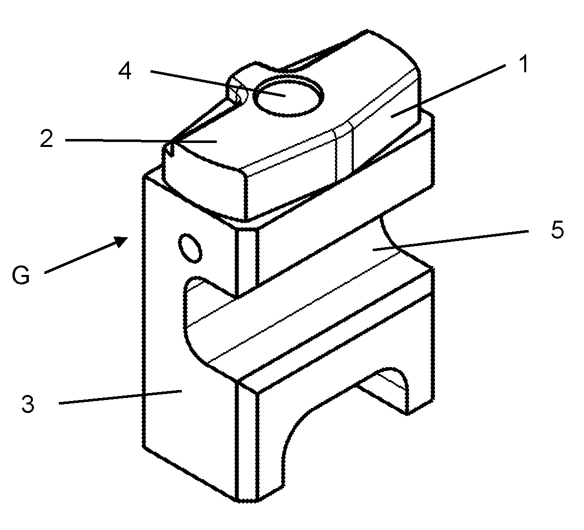
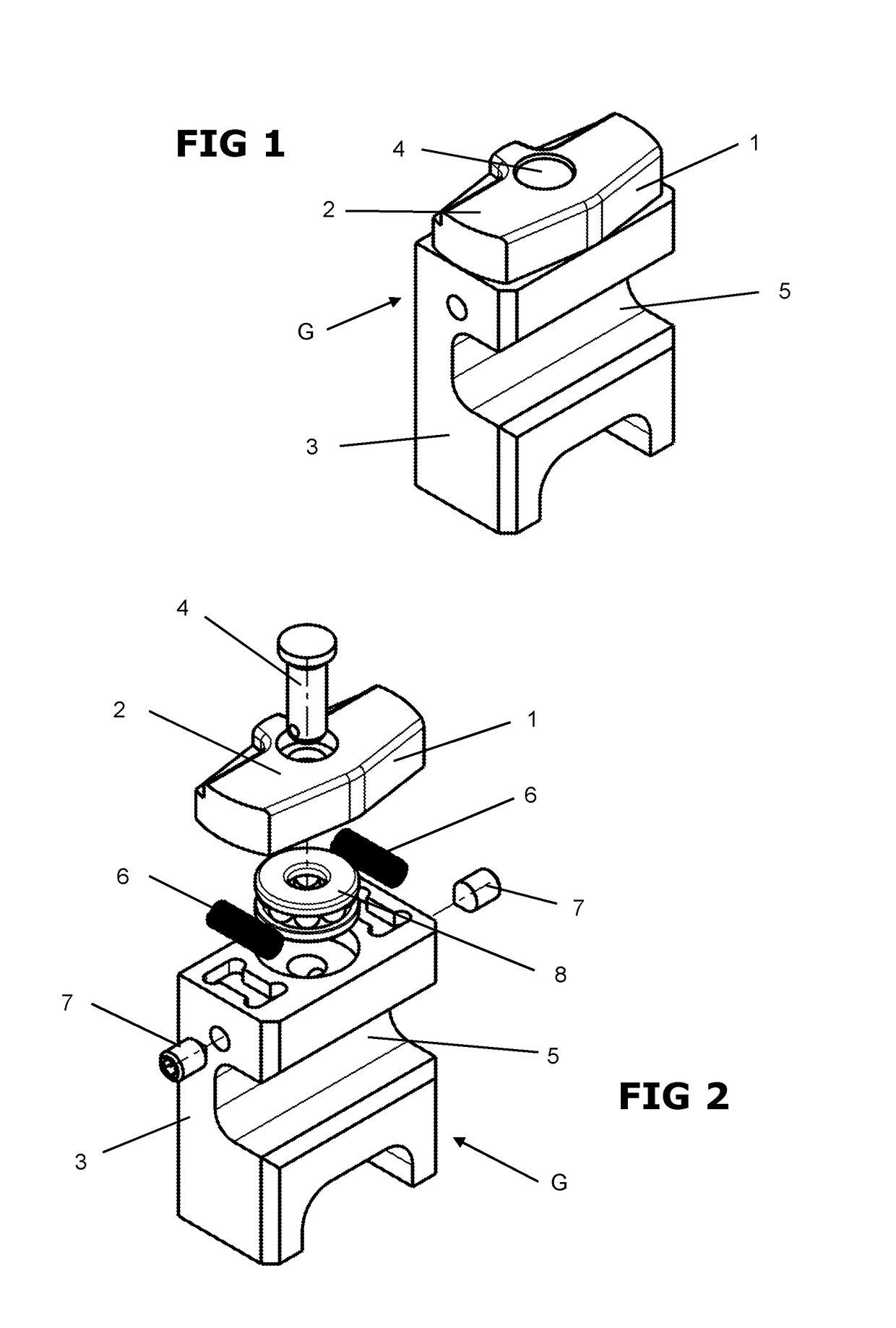
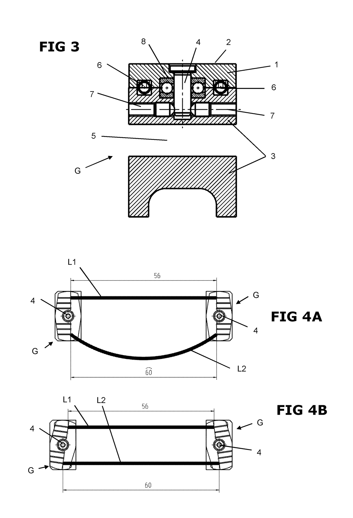
[0038]FIG. 1 shows a perspective view of a gripper jaw G, as is used in conductor grippers GA that clamp the conductors L1, L2 to be twisted in twisting heads V for example (see FIG. 8) for the twisting process. Conductor grippers GA of such kind may also be provided for pulling the conductors L1, L2 in drawing in devices or for transferring conductors L1, L2 to twisting heads or the like, for example, via transfer devices. Conductors L1, L2 may be electrical or optical conductors, such as wires, cables, cable bundles or optical fibres.

[0039]For the twisting operation within the more precisely defined meaning, that is to say twisting the mutually opposite conductor ends relative to each other, at least one gripper jaw G is movable relative to a second, opposing gripper jaw by means of a drive assembly. The two gripper jaws G are advantageously of the same construction. Both gripper jaws G are fastened to a carrier frame or the twisting head V on which said gripper jaws G are mounted...


PUM

PropertyMeasurementUnit
angleaaaaaaaaaa
restoring forceaaaaaaaaaa
elasticaaaaaaaaaa

Abstract

A gripper jaw (G) for a conductor gripper (GA) for a pair of electrical or optical conductors (L1, L2), such as wires, cables, cable bundles or optical fibers. The conductor gripper (GA) has at least one gripper jaw (G) which is movable, by a drive assembly, relative to a second, oppositely positioned gripper jaw. The gripper jaw comprises at least one plate (1) having a gripper surface (2). The at least one plate (1) having a gripper surface (2) is mounted so as to be rotatable relative to a section that is secured against rotation (3) about an axis that is orientated perpendicularly to the gripper surface (2) and extends substantially through a middle of the gripper surface (2). The fixed section (3) is connected to the drive assembly or constructed therewith.

Description

[0001]This application claims priority from European patent application serial no. 17151522.4 filed Jan. 13, 2017.FIELD OF THE INVENTION[0002]The invention relates to a gripper jaw for a conductor gripper for a pair of electrical or optical conductors, and a conductor gripper for a conductor processing line.BACKGROUND OF THE INVENTION[0003]It is essential for a high-quality twisting process for a conductor pair that the axial tensile force is identical in both conductors. If the conductors are pulled in and fed to the twisting process individually one after the other, the lengths of the conductors may be slightly different. The ends of the conductors are clamped in gripper jaws for twisting. If the lengths of the conductors are different, the sag in the two conductors is different (comparable to overhead power line sag). This differing sag (resulting from slightly different lengths of the individual conductors) results in a tendency to form unequal twisting loops (also called twisti...

Claims


Application Information

Patent Timeline
Patent Type & Authority Applications(United States)
IPC IPC(8): H01B13/02H01B11/02
CPCH01B13/0207H01B11/02H01B13/0036B21F7/00
Inventor KAMPMANN, ROLANDZEISE, MARCUSKEIL, UWE
Owner SCHLEUNIGER HLDG
Why Eureka
Try Eureka