Methods of manufacturing piezoelectric actuator and liquid ejection head, piezoelectric actuator, liquid ejection head, and image forming apparatus

a piezoelectric actuator and actuator technology, applied in the direction of piezoelectric/electrostrictive/magnetostrictive devices, piezoelectric/electrostriction/magnetostriction machines, printing, etc., can solve the problems of deteriorating reducing the performance of the piezoelectric element, and deteriorating the bonding characteristics of the piezoelectric body. , to avoid the effect of deteriora

Inactive Publication Date: 2007-06-21
FUJIFILM CORP
View PDF8 Cites 15 Cited by
  • Summary
  • Abstract
  • Description
  • Claims
  • Application Information

AI Technical Summary

Benefits of technology

[0047] According to the present invention, even if a piezoelectric body which is formed on a main substrate containing iron by means of a thin film formation method (for example, aerosol deposition) is calcined by performing heat treatment at a temperature of 400° C. or above, the iron contained in the main substrate is prevented from diffusing into the piezoelectric body by setting the thickness of the first metal oxide film to 0.1 μm or more, thus avoiding deterioration in the performance of the piezoelectric body and decline in the reliability of the piezoelectric body. Furthermore, by setting the thickness of the first metal oxide film to 3.5 μm or less, the function of the diaphragm (prescribed amount of displacement) can be ensured.

Problems solved by technology

If the iron diffuses into the piezoelectric body, the performance decline, such as reduction of the piezoelectric d constant and the decline of the insulating properties of the piezoelectric element, may arise.
(sol gel method), and therefore, in a case of a stainless steel substrate used for the diaphragm, the iron contained in the diaphragm diffuses into a piezoelectric element and degrades the performance of the piezoelectric element.
Furthermore, it is required for the annealing process for piezoelectric elements deposited by AD (aerosol deposition) to be carried out in a normal air atmosphere, and hence there are possibilities that the surface of the diaphragm to be annealed simultaneously with the annealing of the piezoelectric elements is oxidized, thus leading to a decline in the durability of the diaphragm and deterioration of its bonding characteristics with respect to other members.

Method used


Image

  • Methods of manufacturing piezoelectric actuator and liquid ejection head, piezoelectric actuator, liquid ejection head, and image forming apparatus
  • Methods of manufacturing piezoelectric actuator and liquid ejection head, piezoelectric actuator, liquid ejection head, and image forming apparatus
  • Methods of manufacturing piezoelectric actuator and liquid ejection head, piezoelectric actuator, liquid ejection head, and image forming apparatus

Examples


further embodiment

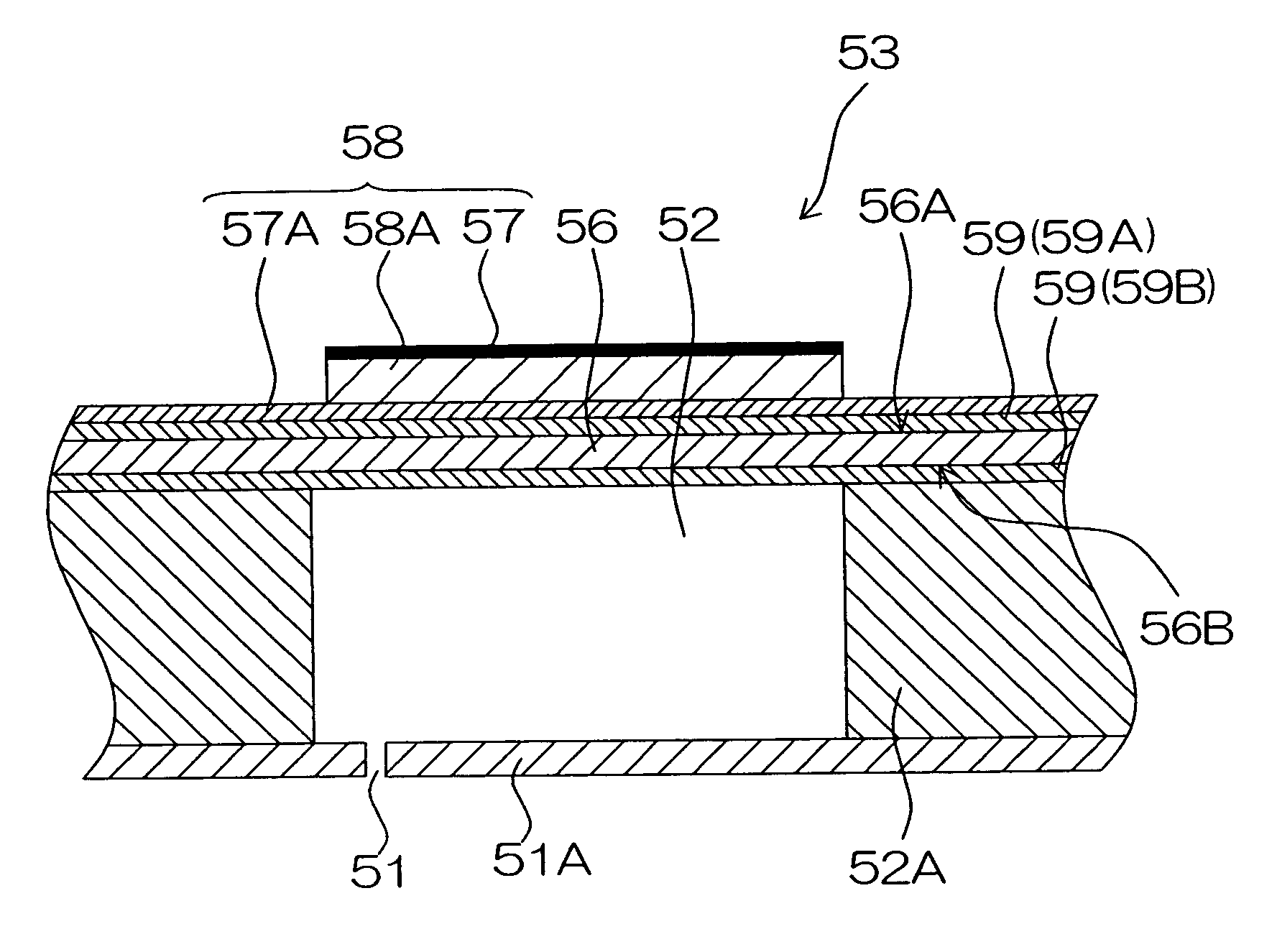
[0146] Next, a further embodiment of the present invention is described below. FIG. 8 is a diagram showing a further mode of the ink chamber units 53 as shown in FIG. 4A, and FIG. 9 is a flowchart showing a manufacturing process for the head 50 comprising the ink chamber units 53′ as shown in FIG. 8. In FIGS. 8 and 9, items which are the same as or similar to those in FIGS. 4A and 7 are labeled with the same reference numerals, and description thereof is omitted here.

[0147] In each ink chamber unit 53′ as shown in FIG. 8, the metal oxide film 59 (59A) is formed on the first surface 56A of the diaphragm 56, and the metal oxide films 59 (59B′) are formed on the parts 100 of the second surface 56B of the diaphragm 56 which form the inner wall surfaces (ceiling faces) of the pressure chambers 52.

[0148] Moreover, the metal oxide films 59 are also formed on the inner wall surfaces (side wall surfaces) 102 of each pressure chamber 52 in the liquid chamber substrate 52A, and on the bondin...


PUM

PropertyMeasurementUnit
thicknessaaaaaaaaaa
thicknessaaaaaaaaaa
temperatureaaaaaaaaaa

Abstract

The method of manufacturing a piezoelectric actuator includes the steps of: forming a first metal oxide film which contains at least one element of aluminum, zirconium and silicon and has a film thickness of not less than 0.1 μm and not greater than 3.5 μm, on a first surface of a main substrate containing iron; forming a piezoelectric element including a piezoelectric body formed by a thin film formation method, on the first metal oxide film formed on the first surface of the main substrate; and calcining the piezoelectric body by carrying out heat treatment at a temperature of not less than 400° C., in a state where the piezoelectric element has been formed on the first metal oxide film formed on the first surface of the main substrate.

Description

BACKGROUND OF THE INVENTION [0001] 1. Field of the Invention [0002] The present invention relates to a method of manufacturing a piezoelectric actuator, a method of manufacturing a liquid ejection head, a piezoelectric actuator, a liquid ejection head and an image forming apparatus, and more particularly, to technology for manufacturing a liquid ejection head which ejects liquid from a nozzle and a structure for such a liquid ejection head. [0003] 2. Description of the Related Art [0004] An inkjet recording apparatus is known which includes a recording head (liquid ejection head) in which the wall surface of a pressure chamber is deformed through the displacement of a piezoelectric element, and ink inside the pressure chamber is pressurized, thereby causing an ink droplet to be ejected from a nozzle connected to the pressure chamber. [0005] In recent years, since higher levels of integration have been sought for recording heads (which is, hereinafter, simply referred to as “head”) u...

Claims


Application Information

Patent Timeline
Patent Type & Authority Applications(United States)
IPC IPC(8): H02N2/00B41J2/055B41J2/045B41J2/135B41J2/14B41J2/145B41J2/155B41J2/16H01L41/09H01L41/187H01L41/22H01L41/319
CPCB41J2/14233B41J2/161B41J2/1631B41J2/1632B41J2/1642B41J2/1646H01L41/0973H01L41/314H10N30/2047H10N30/074
Inventor TSUKAMOTO, RYUJI
Owner FUJIFILM CORP
Why Eureka
Try Eureka