Conversion of solid state source output to virtual source

a technology of virtual source and solid state source, which is applied in the direction of optical radiation measurement, light control, light guide details, etc., can solve the problems of insufficient light intensity, unfavorable lighting effect, and inability to provide such a small output area

Inactive Publication Date: 2007-06-21
ADVANCED OPTICAL TECH
View PDF99 Cites 67 Cited by
  • Summary
  • Abstract
  • Description
  • Claims
  • Application Information

AI Technical Summary

Problems solved by technology

The modulation requires complex circuitry to implement.
In some applications, the LEDs may represent undesirably bright sources if viewed directly.
As the output power of solid state light emitting elements increases, the intensity provided over such a small output area represents a potentially hazardous light source.
Increasingly, direct observation of such sources, particularly for any substantial period of time, may cause eye injury.
Also, the direct illumination from LEDs providing multiple colors of light has not provided optimum combination throughout the field of illumination.
Pixelation often is a problem with prior solid state lighting devices.
Another problem arises from long-term use of LED type light sources.
This increases power consumption.
In some cases, the circuitry may not be able to provide enough light to maintain the desired light output level.
As performance of the LEDs of different colors declines differently with age (e.g. due to differences in usage), it may be difficult to maintain desired relative output levels and therefore difficult to maintain the desired spectral characteristics of the combined output.
Temperature induced changes in performance cause changes in the spectrum of light output.
However, this patent does not discuss particular color combinations or effects or address specific issues related to lighting using one or more solid state light emitting elements.

Method used


Image

  • Conversion of solid state source output to virtual source
  • Conversion of solid state source output to virtual source
  • Conversion of solid state source output to virtual source

Examples


Embodiment Construction

[0047] In the following detailed description, numerous specific details are set forth by way of examples in order to provide a thorough understanding of the relevant teachings. However, it should be apparent to those skilled in the art that the present teachings may be practiced without such details. In other instances, well known methods, procedures, components, and circuitry have been described at a relatively high-level, without detail, in order to avoid unnecessarily obscuring aspects of the present concepts. Reference now is made in detail to the examples illustrated in the accompanying drawings and discussed below.

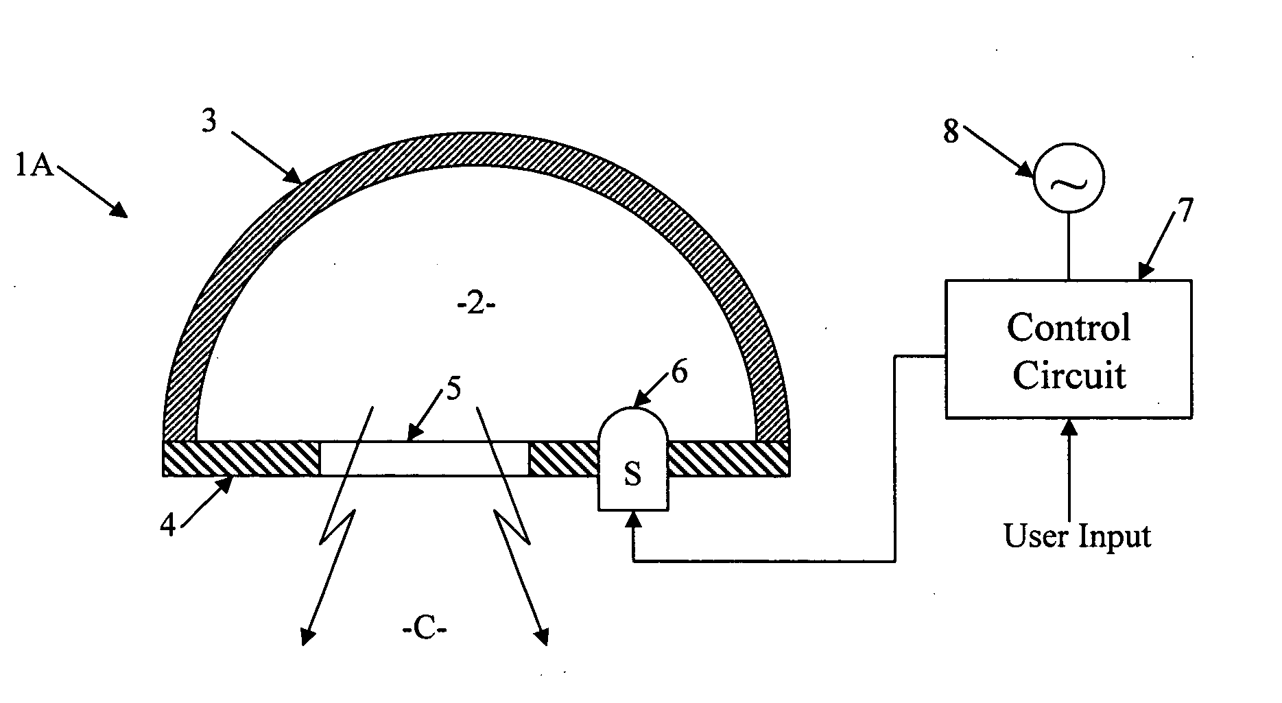
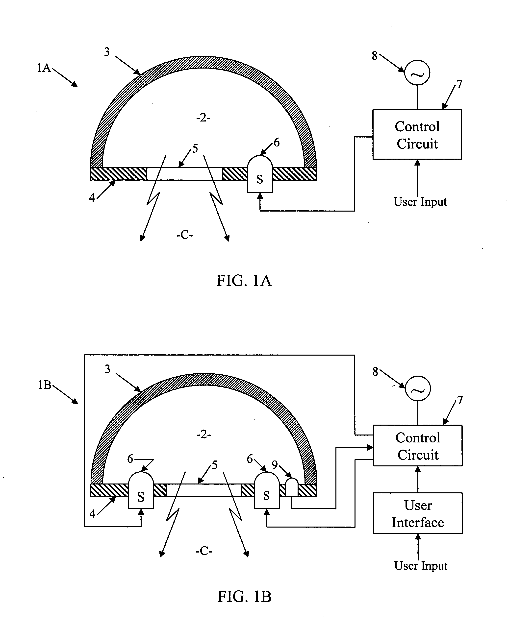
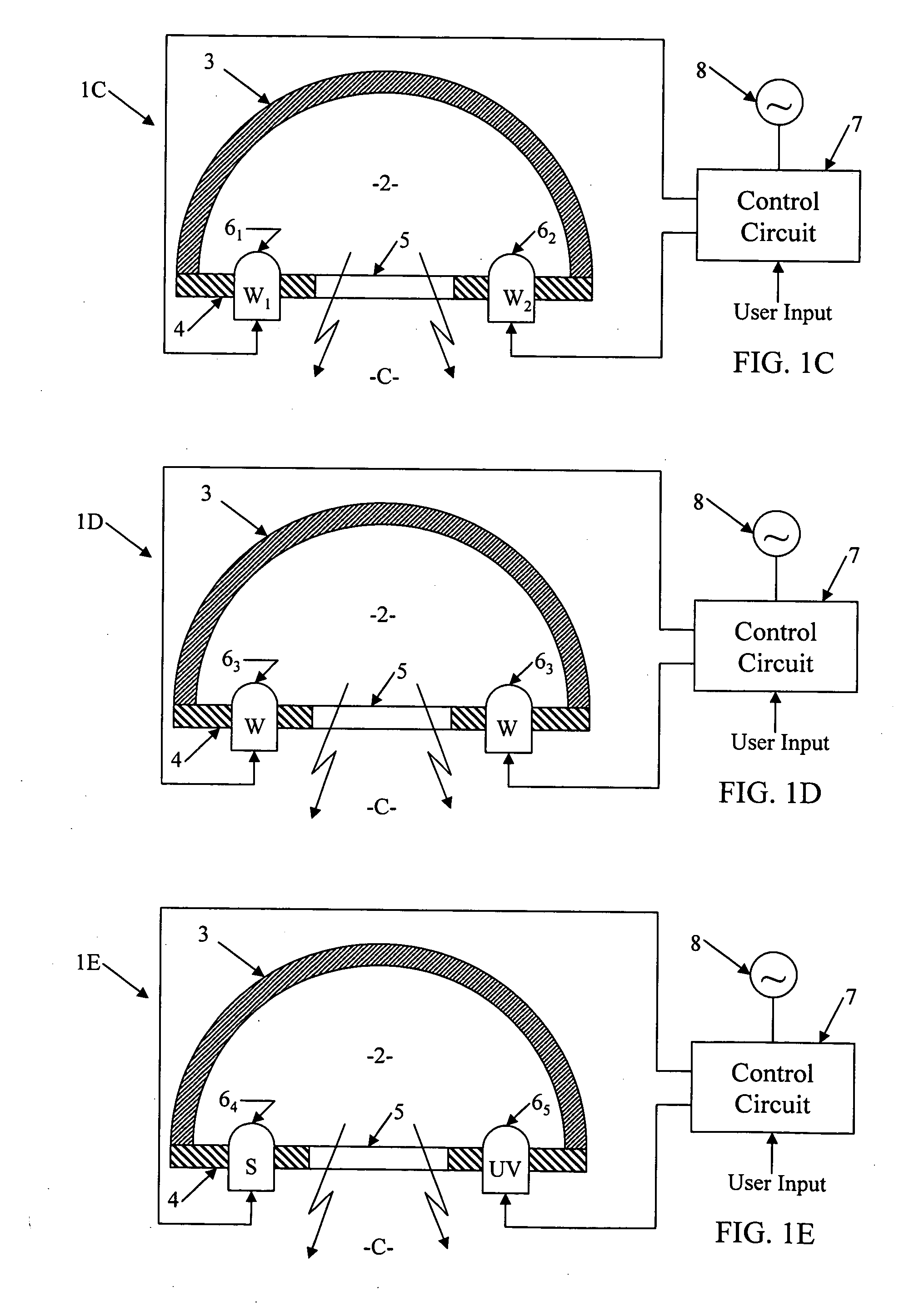
[0048] The techniques disclosed herein convert one or more solid state light sources of relatively small areas (“point sources”) into a virtual source of a larger area. Although other technologies for diffuse processing of light may be used to form the virtual source output, the examples use optical cavity processing. The light output forms a virtual output in that ...


PUM

PropertyMeasurementUnit
reflectivityaaaaaaaaaa
areaaaaaaaaaaa
reflectivityaaaaaaaaaa

Abstract

A light fixture converts source light from one or more solid state light emitting elements to a virtual light source output. An optical element receives and diffuses light from the solid state emitters to form a processed light for the virtual source output. The optical element forms light that is relatively uniform, for example having a substantially Lambertian distribution and / or having a maximum-to-minimum intensity ratio of 2 to 1 or less over the optical area of the virtual source. In the examples, the diffuse optical processing element comprises a cavity having at least one diffusely reflective surface, and the emitting elements supply light into the cavity at locations that result in reflection and diffusion before emission through an aperture of the cavity. The aperture or a downstream processing element appears as the virtual source of the processed light from the cavity.

Description

CROSS-REFERENCE TO RELATED APPLICATION [0001] This application is a continuation-in-part of U.S. patent application Ser. No. 11 / 294,564 filed on Dec. 6, 2005, which is a continuation of U.S. patent application Ser. No. 10 / 832,464, filed Apr. 27, 2004 now U.S. Pat. No. 6,995,355, which is a continuation-in-part of U.S. patent application Ser. No. 10 / 601,101, filed Jun. 23, 2003, the disclosures of which are entirely incorporated herein by reference; and this application claims the benefits of the filing dates of those earlier applications.TECHNICAL FIELD [0002] The present subject matter relates to techniques and equipment to provide lighting, particularly in a manner to convert light from one or more solid state light emitting elements into a virtual source, e.g., exhibiting highly uniform output emissions and / or light emissions of a desired spectral characteristic. BACKGROUND [0003] An increasing variety of lighting applications require a precisely controlled spectral characteristi...

Claims


Application Information

Patent Timeline
Patent Type & Authority Applications(United States)
IPC IPC(8): H05B41/36
CPCF21K9/54F21V2200/13F21S10/02F21V5/002F21V5/008F21V7/0008F21V7/22F21V11/10F21V14/06F21V23/0442F21W2131/406F21Y2101/02F21Y2113/00F21Y2113/005F21Y2113/02G01J1/08G01J3/02G01J3/0216G01J3/0218G01J3/0254G01J3/0256G01J3/0264G01J3/0286G01J3/10G01J3/50G01J3/501G02B5/0252G02B5/0278G02B5/0284G02B6/0008G03B15/06G05D25/02G09F13/0404G09F13/06G09F13/14G09F13/22H05B33/0803H05B33/0812H05B33/0842H05B33/0863H05B33/0869H05B33/0872H05B35/00Y02B20/343F21S2/00F21K9/62F21Y2113/13F21Y2113/20F21Y2115/10F21V7/24F21V7/28H05B45/00H05B45/20H05B45/22H05B45/395Y02B20/30
Inventor RAINS, JACK C. JR.MAY, DON F.RAMER, DAVID P.
Owner ADVANCED OPTICAL TECH
Why Eureka
Try Eureka