System and method for standoff microwave imaging

a standoff microwave and imaging technology, applied in the field of standoff microwave imaging, can solve the problems of inability to identify concealed weapons or other contraband, limited sensitivity of digital cameras, and inability to image opaque or concealed objects, etc., to achieve the effect of reducing the volume and reducing the number of voxels in the imag

Inactive Publication Date: 2007-06-21
AGILENT TECH INC
View PDF21 Cites 49 Cited by
  • Summary
  • Abstract
  • Description
  • Claims
  • Application Information

AI Technical Summary

Benefits of technology

[0011] In another embodiment, to minimize the size of the volume, and hence the number of voxels in the microwave image, the microwave imaging system is augmented with an optical imaging system configured to capture an optical image of an object within the volume and to produce optical image data representing the optical image. From the optical image data, optical image information can be extracted for use by the processor to identify a region of interest within the volume that is associated with the object. The processor can further control the array to illuminate only targets within the region of interest to produce the microwave image with only that region of interest. In yet another embodiment, the number of voxels in the image can also be reduced by using a coarser resolution in the standoff region than in regions closer to the array.

Problems solved by technology

However, digital cameras have limited sensitivity, and are not capable of imaging opaque or concealed items.
For example, at a point-of-entry into a facility, such as a government building, school, airport or other structure, traditional analog or digital cameras are not able to identify concealed weapons or other contraband (e.g., explosives).
Thus, as the imaging distance increases, the aperture size and cost of the antenna array may become prohibitively high in many situations.
In addition, imaging at large, standoff distances also necessarily increases the scanning volume of the system (i.e., the number of voxels to be scanned grows linearly with distance), which further increases the cost and computational complexity of the microwave imaging system.

Method used


Image

  • System and method for standoff microwave imaging
  • System and method for standoff microwave imaging
  • System and method for standoff microwave imaging

Examples


Embodiment Construction

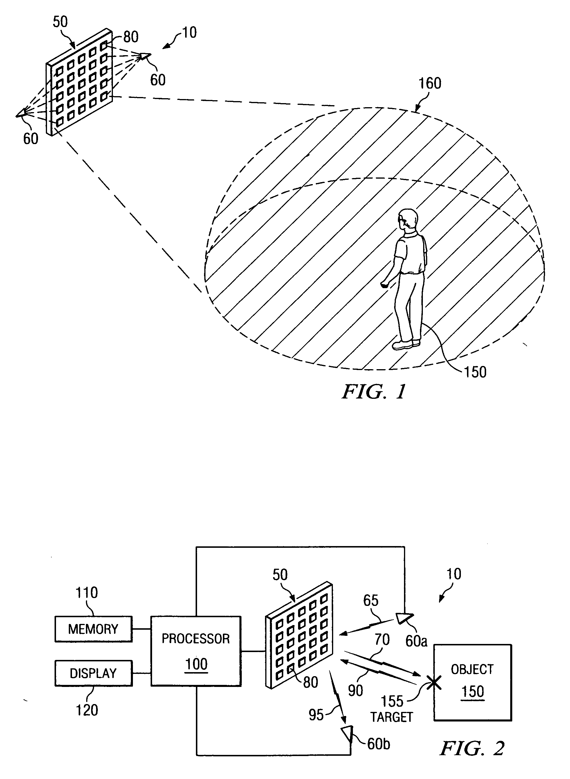
[0026] As used herein, the terms microwave radiation and microwave illumination each refer to the band of electromagnetic radiation having wavelengths between 0.3 mm and 30 cm, corresponding to frequencies of about 1 GHz to about 1,000 GHz. Thus, the terms microwave radiation and microwave illumination each include traditional microwave radiation, as well as what is commonly known as millimeter wave radiation. In addition, as used herein, the term “microwave imaging system” refers to an imaging system operating in the microwave frequency range, and the resulting images obtained by the microwave imaging system are referred to herein as “microwave images.” Furthermore, as used herein, the term “standoff” refers to a distance between an imaging device and an object that is approximately equal to or greater than nine feet. In exemplary embodiments, the term “standoff” refers to a distance between an imaging device and an object of between 9 feet and 450 feet.

[0027] Referring now to FIG...


PUM


Abstract

A microwave imaging system for performing standoff microwave imaging includes an antenna array with a plurality of antenna elements, each capable of being programmed with a respective direction coefficient to direct microwave illumination toward a target within a volume that includes a standoff region, and each capable of being programmed with a respective additional direction coefficient to receive reflected microwave illumination reflected from the target. A processor measures an intensity of the reflected microwave illumination to determine a value of a voxel within a microwave image of the volume. The processor constructs the microwave image with a resolution sufficient to identify objects within the standoff region.

Description

CROSS-REFERENCE TO RELATED APPLICATIONS [0001] This application is related by subject matter to U.S. patent application Ser. No. ______ (Attorney Docket No. 10040151), entitled “A Device for Reflecting Electromagnetic Radiation,” U.S. patent application Ser. No. ______ (Attorney Docket No. 10040580), entitled “Broadband Binary Phased Antenna,” and U.S. patent application Ser. No. 10 / 996,764, entitled “System and Method for Security Inspection Using Microwave Imaging” all of which were filed on Nov. 24, 2004. [0002] This application is further related by subject matter to U.S. patent application Ser. No. ______ (Attorney Docket No. 10050095), entitled “System and Method for Efficient, High-Resolution Microwave Imaging Using Complementary Transmit and Receive Beam Patterns,” U.S. patent application Ser. No. 11 / 088,831, entitled “System and Method for Inspecting Transportable Items Using Microwave Imaging,” U.S. patent application Ser. No. ______ (Attorney Docket No. 10050533), entitle...

Claims


Application Information

Patent Timeline
Patent Type & Authority Applications(United States)
IPC IPC(8): G01S13/89
CPCG01S13/89
Inventor BAHARAV, IZHAKTABER, ROBERT C.LEE, GREGORY S.NEIL, JOHN M.CORREDOURA, PAUL L.WEEMS, WILLIAMYOUNG, JAMES E.
Owner AGILENT TECH INC
Why Eureka
Try Eureka