Method of producing elliptically polarizing plate and image display using the elliptically polarizing plate

a technology applied in the field of elliptically polarizing plates and image displays, can solve the problems of film quality variation, high cost and long time, and inability to exhibit the desired optical characteristics (such as the functions of /4 plates) over a wide wavelength range, and achieve low cost, no waste, and high production efficiency

Inactive Publication Date: 2007-06-21
NITTO DENKO CORP
View PDF22 Cites 15 Cited by
  • Summary
  • Abstract
  • Description
  • Claims
  • Application Information

AI Technical Summary

Benefits of technology

[0010] The present invention has been made in view of solving the conventional problems as described above, and an object of the present invention is therefore to provide: a method of producing a broadband, wide viewing angle, and thin elliptically polarizing plate having excellent characteristics in an oblique direction as well at very high efficiency; an elliptically polarizing plate obtained through the method; and an image display using the elliptically polarizing plate.
[0011] The inventors of the present invention have conducted extensive studies on a relationship among an absorption axis of a polarizer and slow axes of a λ / 4 plate and a λ / 2 plate, and have found that excellent broadband and wide viewing angle characteristics can be obtained when angle between the absorption axis and the respective slow axes are in a specific relationship, to thereby complete the present invention.
[0028] As described above, according to the present invention, the slow axis of the first birefringent layer can be set in any desired directions in the alignment treatment for the transparent protective film, and thus a continuous polarizing film (polarizer) stretched in a longitudinal direction (that is, a film having an absorption axis in a longitudinal direction) can be used. In other words, a continuous transparent protective film which has been subjected to the alignment treatment at a predetermined angle with respect to its longitudinal direction and a continuous polarizing film (polarizer) may be continuously attached together while the respective longitudinal directions being arranged in the same direction (by so-called roll to roll). Thus, an elliptically polarizing plate can be obtained at very high production efficiency. According to the method of the present invention, the transparent protective film or the polarizer need not be cut out obliquely with respect to its longitudinal direction (stretching direction) for lamination. As a result, angles of optical axes do not vary with respect to every cut-out film, resulting in an elliptically polarizing film without variation in quality with respect to every product. Further, no wastes are produced by cutting of the film, and the elliptically polarizing plate can be obtained at low cost and production of a large polarizing plate is facilitated. Furthermore, according to an embodiment of the present invention, a polymer film stretched in a width direction and having a slow axis in the width direction is used as the polymer film forming the second birefringent layer. Thus, long sides of the polarizer and the polymer film may be continuously attached together, and an elliptically polarizing plate can be obtained at very high production efficiency. The thus-obtained elliptically polarizing plate is optimized to have angles α and β in a relationship represented by an expression 2α+40°<β<2α+50° (wherein, α represents an angle between an absorption axis of the polarizer and the slow axis of the first birefringent layer (λ / 2 plate), and β represents an angle between the absorption axis of the polarizer and the slow axis of the second birefringent layer (λ / 4plate)), to thereby provide an image display with broadband and wide viewing angle. The relationship is comprehensive, and requires no studies on lamination direction depending on products by trial and error. That is, the relationship may be used for almost all combinations of the polarizer, λ / 2 plate, and λ / 4 plate, to thereby realize excellent circular polarization characteristics. As a result, optimization of the circular polarization characteristics can be generalized and facilitated.

Problems solved by technology

Thus, the λ / 4 plate has a problem in that it cannot exhibit desired optical characteristics (such as functions of the λ / 4 plate) over a wide wavelength range.
However, such a film has problems in cost.
In the case where a film is cut out and then attached as described above, angles between optical axes may vary with respect to every cut-out film, for example, which may result in problems of variation in quality with respect to every product and production requiring high cost and long time.
Further problems include increased waste by cutting out of the films, and difficulties in production of large films.
However, the method has a problem in that the adjustment involves difficulties.
Further, at present, an angle between an absorption axis of a polarizing film and a slow axis of each retardation plate is adjusted with respect to every product, and comprehensive means for optimization of the angle has not been found yet.

Method used


Image

  • Method of producing elliptically polarizing plate and image display using the elliptically polarizing plate
  • Method of producing elliptically polarizing plate and image display using the elliptically polarizing plate
  • Method of producing elliptically polarizing plate and image display using the elliptically polarizing plate

Examples


example 1

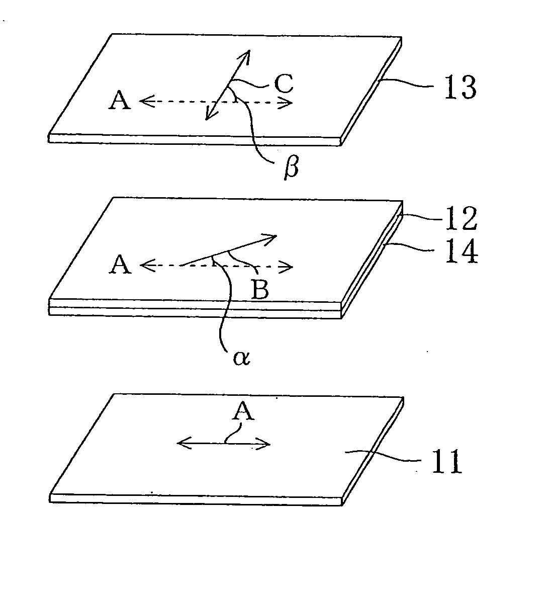
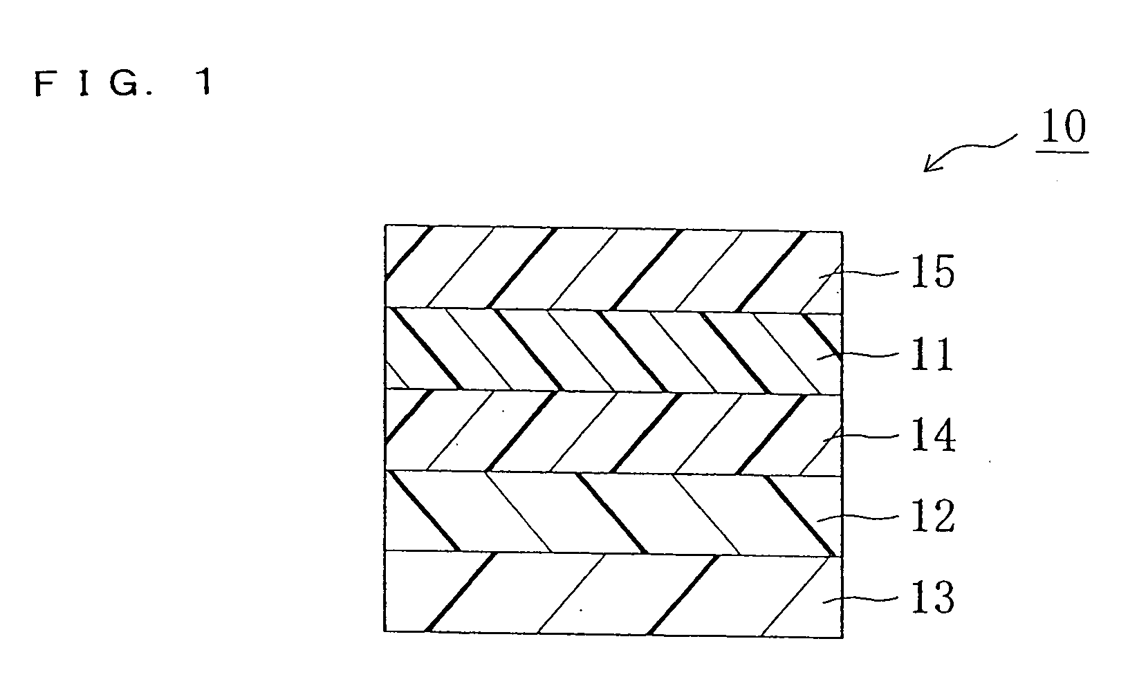
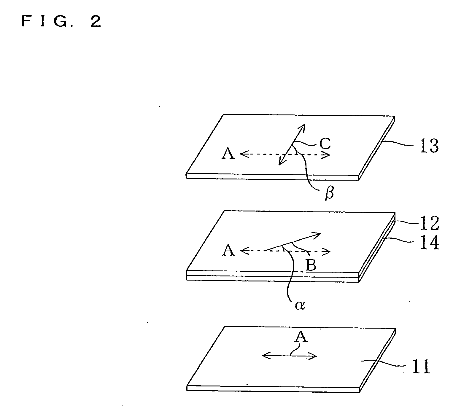
I. Preparation of Elliptically Polarizing Plate as Shown in FIG.

I-a. Alignment Treatment for transparent Protective Film (Preparation of Alignment Substrate)

[0117] Transparent protective films were subjected to alignment treatment, to thereby prepare alignment substrates (eventually, protective layers).

[0118] Substrates (1) to (8): A PVA film (thickness of 0.1 μm) was formed on a surface of a TAC film (thickness of 40 μm). Then, the surface of the PVA film was subjected to rubbing at a rubbing angle shown in Table 1 by using a rubbing cloth, to thereby form each of alignment substrates.

[0119] Substrates (9) and (10): A TAC film (thickness of 40 μm) was subjected to rubbing at a rubbing angle shown in Table 1 by using a rubbing cloth, to thereby form each of alignment substrates.

[0120] Substrates (11) and (12): A silane coupling agent (KBM-503, trade name; available from Shin-Etsu Silicones) was applied onto a surface of a TAC film (thickness of 40 μm). The surface of the sila...

example 2

[0127] The elliptically polarizing plates A01 were superimposed to measure a contrast ratio. Table 5 reveals that the elliptically polarizing plate had a relationship represented by an expression β=2α+44°. The elliptically polarizing plate had the minimum angle of 40° and maximum angle of 50° for contrast 10 in all directions, and a difference between the maximum and minimum angles of 10°. The minimum angle of 40° for contrast 10 in all directions was at a preferred level in practical use. Further, the difference between the maximum and minimum angles of 10° was small and was also at a very preferred level in practical use, and thus the elliptically polarizing plate had balanced visual characteristics.

example 3

[0128] The elliptically polarizing plates A21 were superimposed to measure a contrast ratio. Table 5 reveals that the elliptically polarizing plate had a relationship represented by an expression β=2α+49°. The elliptically polarizing plate had the minimum angle of 40° and maximum angle of 60° for contrast 10 in all directions, and a difference between the maximum and minimum angles of 20°. The minimum angle of 40° for contrast 10 in all directions was at a preferred level in practical use.


PUM

PropertyMeasurementUnit
angleaaaaaaaaaa
angleaaaaaaaaaa
angleaaaaaaaaaa

Abstract

The present invention provides: a method of producing a broadband and wide viewing angle elliptically polarizing plate having excellent characteristics in an oblique direction as well; and an image display using the elliptically polarizing plate obtained through the method. The method of producing an elliptically polarizing plate according to the present invention includes the steps of: subjecting a surface of a transparent protective film to alignment treatment; forming a first birefringent layer by applying a liquid crystal composition onto the surface of the transparent protective film subjected to the alignment treatment; laminating a polarizer on a surface of the transparent protective film opposite to the surface subjected to the alignment treatment; and forming a second birefringent layer by laminating a polymer film on a surface of the first birefringent layer, in which the elliptically polarizing plate has a relationship represented by the following expression (1) 2α+40°<β<2α+50°  (1) in the expression (1), α represents an angle between an absorption axis of the polarizer and an alignment direction of the transparent protective film, and β represents an angle between the absorption axis of the polarizer and a slow axis of the second birefringent layer.

Description

CROSS-REFERENCE TO RELATED APPLICATION [0001] This application is a Divisional application of application Ser. No. 11 / 169,964, filed Jun. 30, 2005, the entire disclosure of which is hereby incorporated by reference.BACKGROUND OF THE INVENTION [0002] 1. Field of the Invention [0003] The present invention relates to an elliptically polarizing plate, and to an image display using the same. The present invention more specifically relates to a method of producing a broadband and wide viewing angle elliptically polarizing plate having excellent characteristics in an oblique direction as well at very high efficiency, to an elliptically polarizing plate obtained through the method, and to an image display using the elliptically polarizing plate. [0004] 2. Description of the Related Art Various optical films each having a polarizing film and a retardation plate in combination are generally used for various image displays such as a liquid crystal display and an electroluminescence (EL) displa...

Claims


Application Information

Patent Timeline
Patent Type & Authority Applications(United States)
IPC IPC(8): G02B5/30G02B27/28
CPCG02B5/3016G02B5/30G02F1/1335
Inventor KAWAMOTO, IKUOUMEMOTO, SEIJIKAMIJOU, TAKASHI
Owner NITTO DENKO CORP
Why Eureka
Try Eureka