
Compensation free illumination of instrument cluster display

a technology of instrument clusters and light guides, applied in the field of vehicle instrument clusters, can solve the problems of poor light efficiency provided by instrument clusters utilizing compensation, known light guides that have not satisfactorily provided uniform light distribution over the entire display,

Inactive Publication Date: 2007-06-21
CONTINENTAL AUTOMOTIVE SYST INC
View PDF10 Cites 41 Cited by
  • Summary
  • Abstract
  • Description
  • Claims
  • Application Information

AI Technical Summary

Benefits of technology

The patent describes a light guide assembly for illuminating a display of an instrument cluster. The assembly includes a light receiving portion, a light propagating portion, and a conical surface between them. The light propagating portion has a plurality of lobes that uniformly illuminate the instrument cluster surface. The assembly also includes a reflective surface with a negative sloped section and a positive sloped section. The technical effect of this invention is to provide a more efficient and effective way of illuminating the instrument cluster, which can be seen in the various figures of the patent.

Problems solved by technology

Disadvantageously, known light guides have not satisfactorily provided uniform distribution of light over the entire display.
Disadvantageously, the light efficiency provided by an instrument cluster utilizing compensation may be poor because a large quantity of light produced by the light source is absorbed by the compensation layer.

Method used


Image

  • Compensation free illumination of instrument cluster display
  • Compensation free illumination of instrument cluster display
  • Compensation free illumination of instrument cluster display

Examples


Embodiment Construction

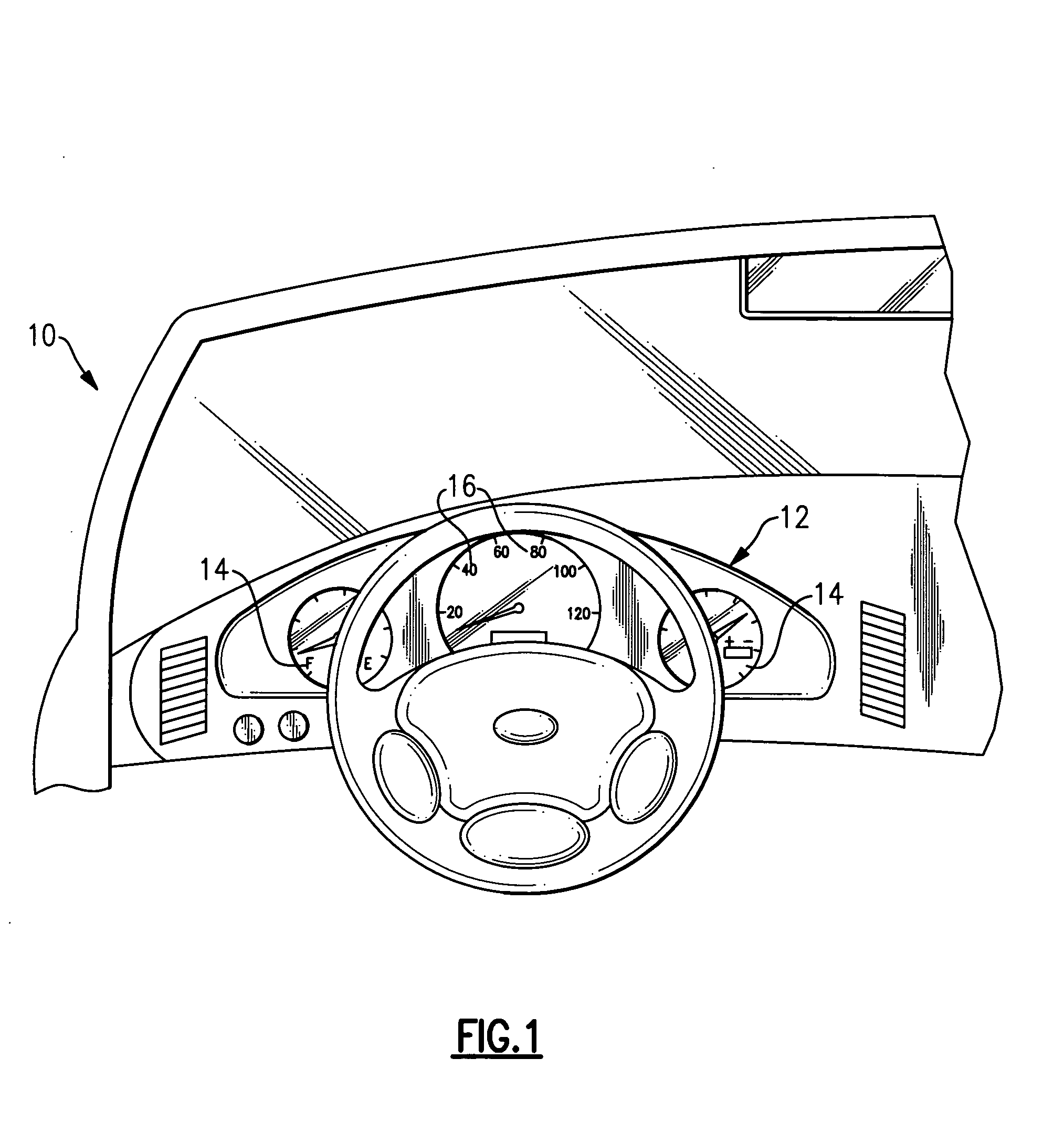
[0016]FIG. 1 illustrates selected portions of a vehicle 10 having an instrument cluster 12, such as a vehicle gauge cluster, that communicates vehicle information to occupants of the vehicle 10. In the illustrated example, the instrument cluster 12 includes a vehicle display 14 having a plurality of graphics 16, such as numbers, letters, or symbols. At least a portion of the vehicle graphics 16 are illuminated from within the instrument cluster 12 for nighttime viewing or for aesthetic purposes, for example.

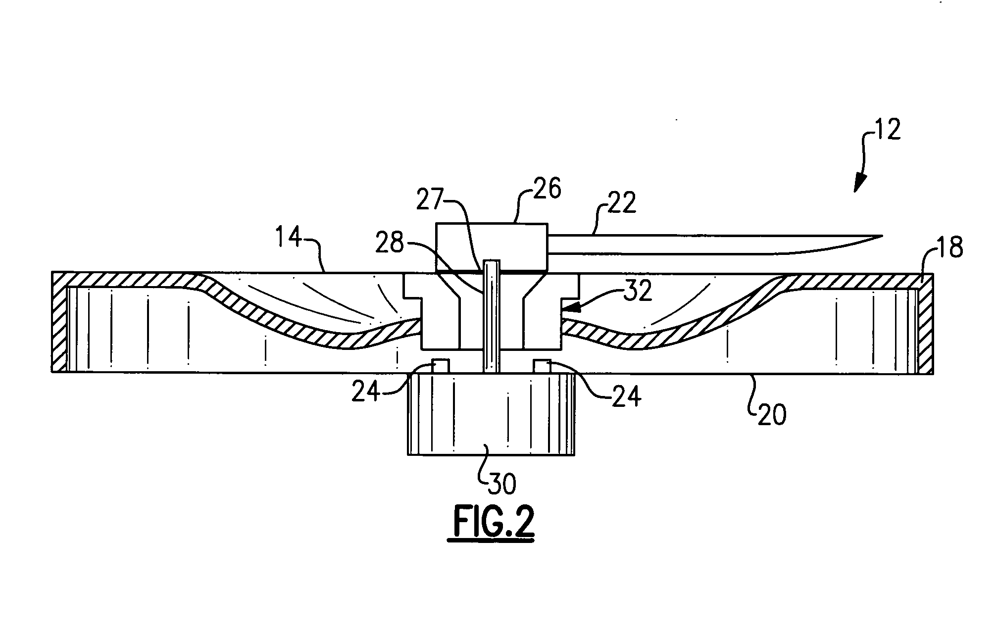
[0017]FIG. 2 shows selected portions of the example instrument cluster 12, including a light housing 18 that supports the display 14 and a circuit board 20, such as a printed circuit board (PCB). A pointer 22 is mounted to the circuit board 20 for movement relative to the display 14 and is used to indicate the current status of the vehicle operating condition. The circuit board 20 also includes a light source 24, such as a light emitting diode (LED), for illuminating the display ...


PUM


Abstract

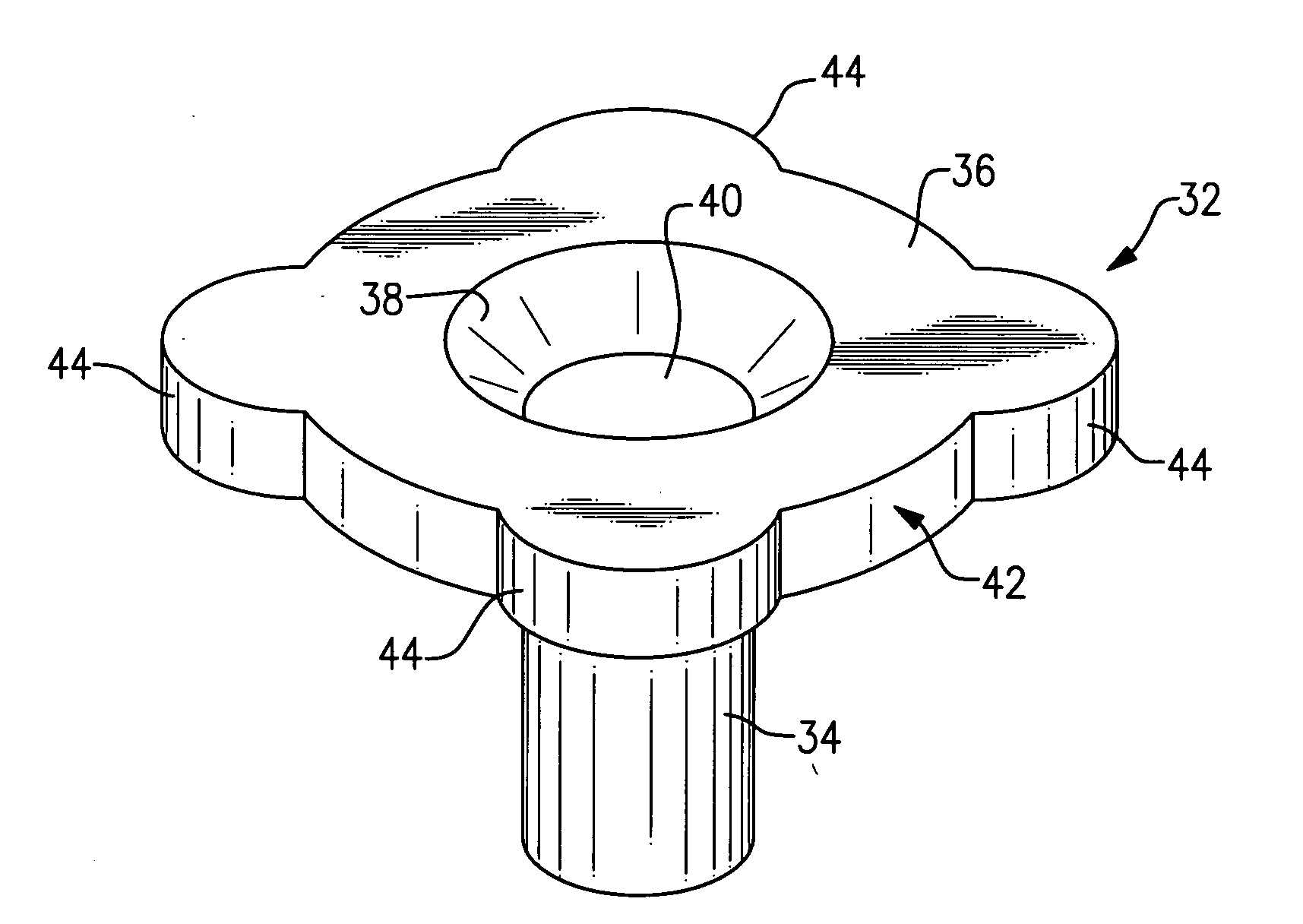
An example light guide assembly for illuminating a display of an instrument cluster includes a light receiving portion, a light propagating portion and a conical surface positioned between the light receiving portion and the light propagating portion. An exterior surface of the light propagating portion includes a plurality of lobes that uniformly illuminate the display as light propagates from the light receiving portion to the conical surface and through the light propagating portion.

Description

CROSS-REFERENCE TO RELATED APPLICATIONS[0001]This application claims priority to U.S. Provisional Application No. 60 / 751,072, filed Dec. 15, 2005.BACKGROUND OF THE INVENTION[0002]The present invention relates to a vehicle instrument cluster, and more particularly to a light guide assembly for an illuminated display that increases light efficiency.[0003]An instrument cluster for a vehicle is traditionally located on a vehicle dashboard and includes several displays or dials that indicate various vehicle operating conditions. For example, an instrument cluster may include a speedometer, a tachometer, an engine condition indicator, and other known types of gauges. These gauges are illuminated to facilitate reading of the information by the vehicle occupants.[0004]Instrument clusters include a printed circuit board (PCB) with electronic components for controlling operation of the instrument clusters. Light sources, such as light emitting diodes (LEDs), are typically mounted to the PCB. ...

Claims


Application Information

Patent Timeline
Patent Type & Authority Applications(United States)
IPC IPC(8): G01D11/28
CPCB60K37/02B60K2350/203B60Q3/004B60Q3/044G01D11/28G02B6/0018G02B6/0028G02B6/0055B60Q3/64B60Q3/14B60K35/60B60K2360/33B60K2360/698
Inventor BIRMAN, VYACHESLAV B.ECKARDT, WERNERRAMIREZ-ALDANA, FRANCISCO
Owner CONTINENTAL AUTOMOTIVE SYST INC
Learn More