LED light with active cooling

a technology of led light and active cooling, which is applied in the direction of semiconductor devices, lighting and heating apparatus, semiconductor devices for light sources, etc., can solve the problems of insufficient heat reduction in high-power led lighting systems, heat dissipation systems, and large amount of heat dissipation

Inactive Publication Date: 2007-06-21
LUMINATION
View PDF54 Cites 168 Cited by
  • Summary
  • Abstract
  • Description
  • Claims
  • Application Information

AI Technical Summary

Problems solved by technology

More specifically, high power LED lighting systems dissipate a substantial amount of heat via terminals or through the die attached in a direct die mount device.
The conventional heat dissipation systems (i.e. radiating a large percentage of heat to a front lens of a lamp) do not adequately reduce heat in higher power LED systems.
Consequently, h...

Method used


Image

  • LED light with active cooling
  • LED light with active cooling
  • LED light with active cooling

Examples


Embodiment Construction

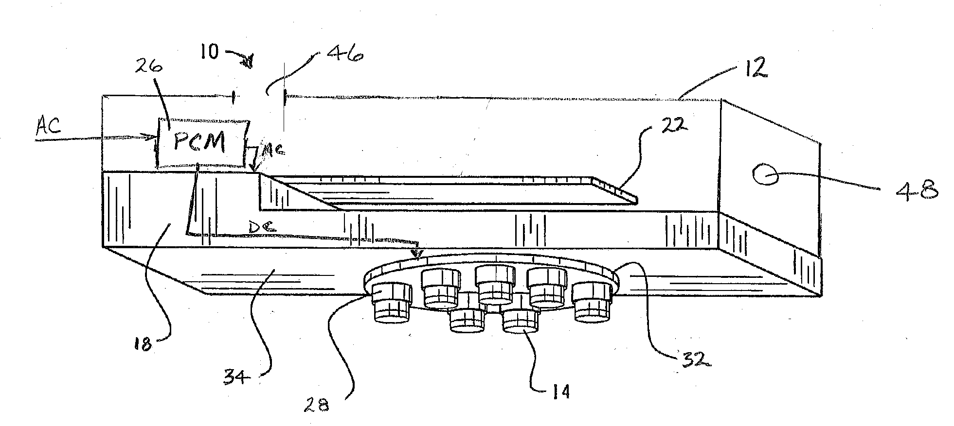
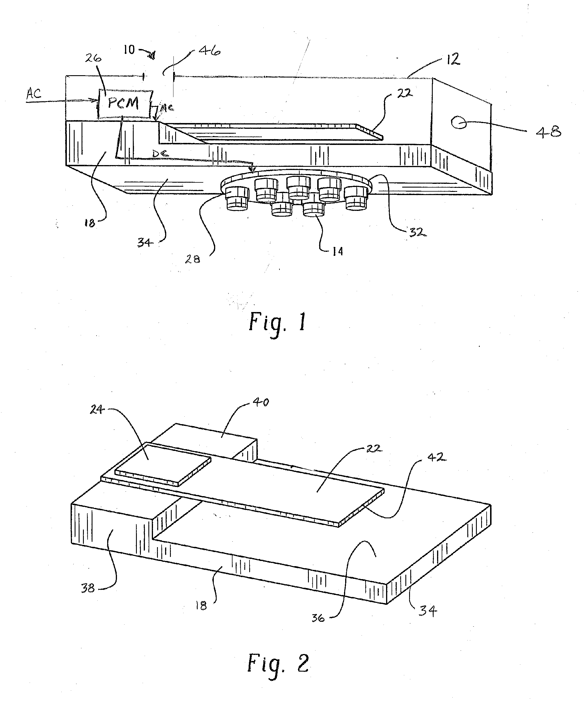
[0035] With reference to FIG. 1, an LED lamp 10 generally includes a housing (or frame) 12, a plurality of LEDs, which in FIG. 1 are provided in LED devices 14 and in FIG. 3 are shown as chip-on-board devices 16, that are in communication with a heat sink 18. A flexible blade 22 oscillates to generate a fluid current to cool the LEDs and, perhaps, other electrical components.

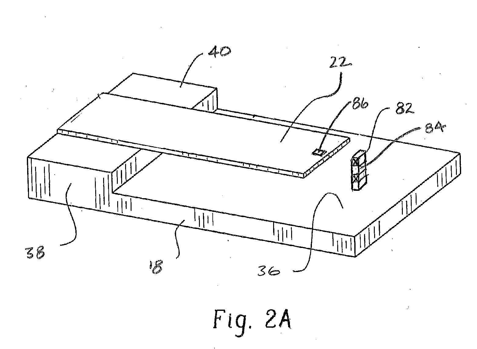
[0036] The flexible blade 22 is driven, i.e. caused to oscillate, by an electronic actuator. One example of an electronic actuator is piezoelectric material 24 that connects to the blade and receives power from a power control module 26 to move the blade to generate a fluid stream that passes over surfaces of the heat sink to cool the LEDs. With reference to FIG. 2A, another example of an electronic actuator can include a coil 82 disposed about a core 84 (depicted schematically) constructed of magnetic material. The embodiment depicted in FIG. 2A, other than not including piezoelectric material, is the same as ...


PUM

PropertyMeasurementUnit
Poweraaaaaaaaaa
Flow rateaaaaaaaaaa
Flexibilityaaaaaaaaaa

Abstract

An LED lamp that includes a piezoelectric fan or synthetic jet to cool component of the lamp is disclosed.

Description

[0001] This application is a continuation-in-part of U.S. patent application Ser. No. 10 / 726,882, which claims priority to U.S. provisional patent application Ser. No. 60 / 459,238 filed Mar. 31, 2003. Both of the aforementioned patent applications are incorporated by reference herein.BACKGROUND [0002] An LED (light emitting diode) generally includes a diode mounted onto a die or chip. The diode is then surrounded by an encapsulant. The die receives electrical power from a power source and supplies power to the diode. The die can be mounted in a die support. To produce a brighter LED, generally, more power is delivered to the LED. [0003] Many LED lighting systems dissipate heat through a different heat transfer path than ordinary filament bulb systems. More specifically, high power LED lighting systems dissipate a substantial amount of heat via terminals or through the die attached in a direct die mount device. The conventional heat dissipation systems (i.e. radiating a large percenta...

Claims


Application Information

Patent Timeline
IPC IPC(8): F21V29/00F21V29/02H01L23/467H01L23/473
CPCF21V29/004F21V29/63F21Y2101/02H01L23/467H01L23/473Y10S362/80F21K9/56F21V3/02F21V23/02F21V3/0481H01L2924/0002F21V29/02F21K9/137F21K9/135H01L2924/00F21K9/232F21K9/233F21K9/64F21Y2115/10F21V29/70F21V3/12
Inventor PETROSKI, JAMES T.ARIK, MEHMET
Owner LUMINATION
Why Eureka
Try Eureka