Cooling systems for stacked laminate CMC vane

a cooling system and cmc vane technology, applied in the field of turbine engines, can solve the problems of inability to meet the requirements of a stationary airflow,

Active Publication Date: 2007-06-21
SIEMENS ENERGY INC
View PDF35 Cites 94 Cited by
  • Summary
  • Abstract
  • Description
  • Claims
  • Application Information

AI Technical Summary

Benefits of technology

[0015] A series of cooling slots can be provided in the forward portion of the first laminate. The cooling slots can extend radially through the first laminate. The cooling slots can be proximate to and can generally follow the outer peripheral surface of the first laminate. Similarly, a series of cooling slots can be provided in the forward portion of the second laminate. The cooling slots can extend radially through the second laminate. The cooling slots can be proximate to and can generally follow the outer peripheral surface of the se

Problems solved by technology

However, material selection alone will not enable the vanes to withstand such an environment.
Though a variety of systems can adequately cool a va

Method used


Image

  • Cooling systems for stacked laminate CMC vane
  • Cooling systems for stacked laminate CMC vane
  • Cooling systems for stacked laminate CMC vane

Examples


Embodiment Construction

[0045] Various cooling systems according to embodiments of the invention will be explained herein in the context of one possible stacked laminate turbine vane construction, but the detailed description is intended only as exemplary. Embodiments of the invention are shown in FIGS. 1-20, but the present invention is not limited to the illustrated structure or application.

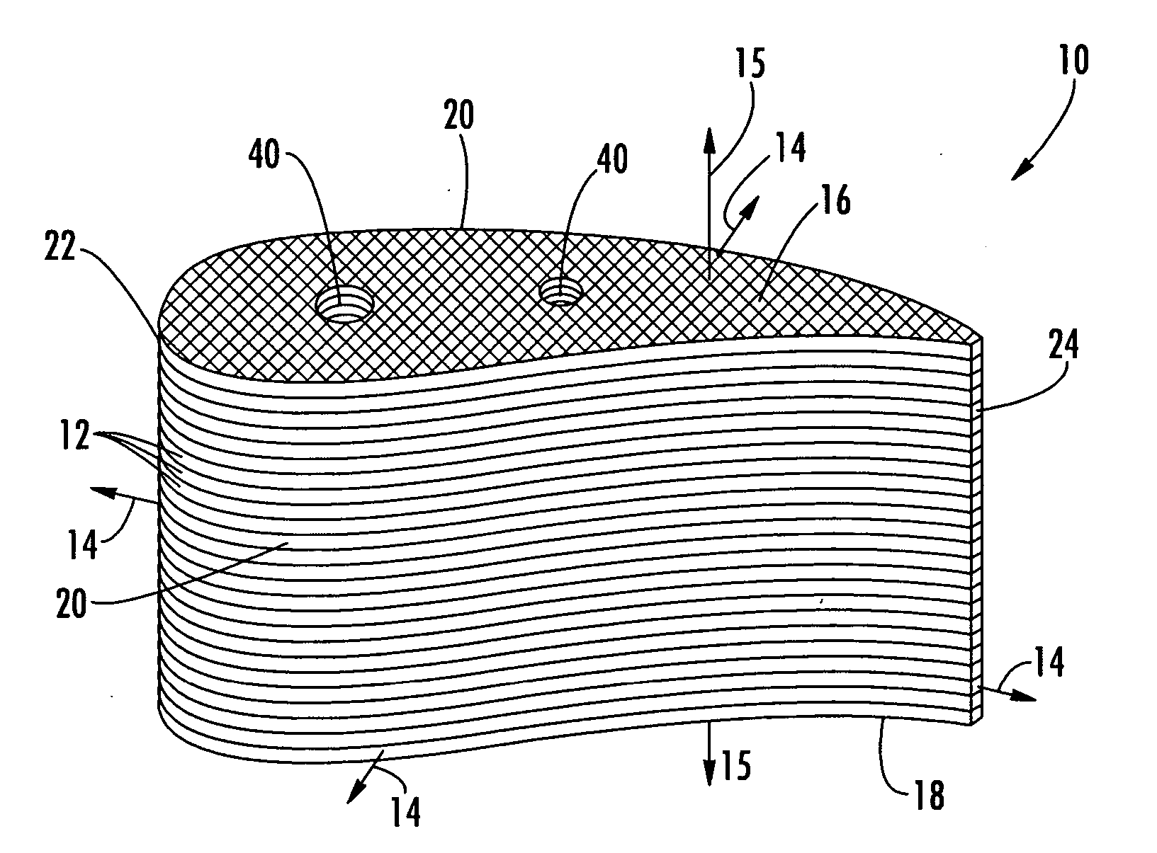
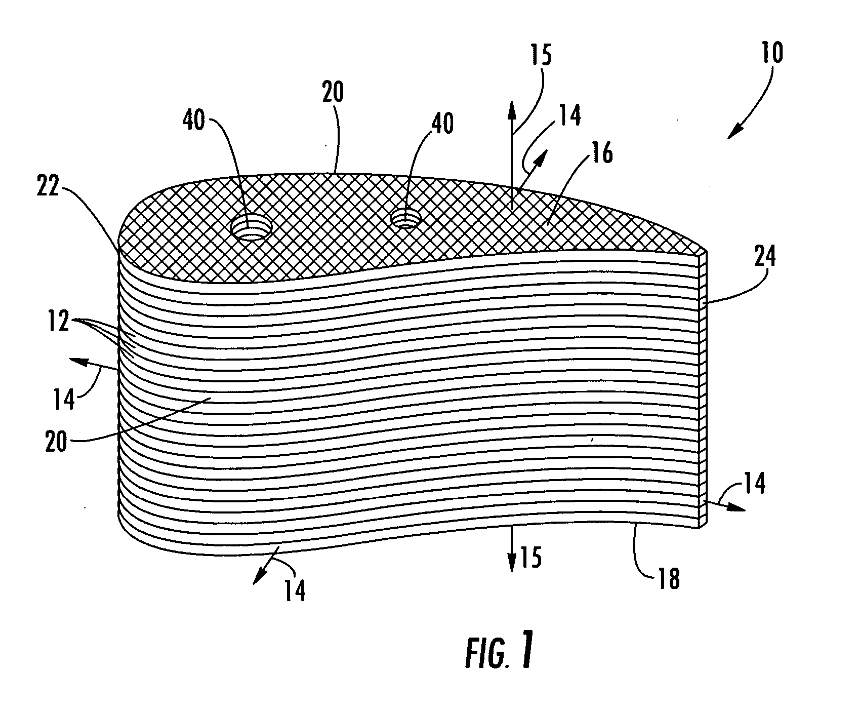
[0046]FIG. 1 shows one possible construction of a turbine vane assembly 10 according to aspects of the invention. The vane 10 can be made of a plurality of CMC laminates 12. The vane 10 can have a radially outer end 16 and a radially inner end 18 and an outer peripheral surface 20. The term “radial,” as used herein, is intended to describe the direction of the vane 10 in its operational position relative to the turbine. Further, the vane assembly 10 can have a leading edge 22 and a trailing edge 24.

[0047] The individual laminates 12 of the vane assembly 10 can be substantially identical to each other; however, one o...


PUM


Abstract

Embodiments of the invention relate to various cooling systems for a turbine vane made of stacked ceramic matrix composite (CMC) laminates. Each airfoil-shaped laminate has an in-plane direction and a through thickness direction substantially normal to the in-plane direction. The laminates have anisotropic strength characteristics in which the in-plane tensile strength is substantially greater than the through thickness tensile strength. Such a vane construction lends itself to the inclusion of various cooling features in individual laminates using conventional manufacturing and forming techniques. When assembled in a radial stack, the cooling features in the individual laminates can cooperate to form intricate three dimensional cooling systems in the vane.

Description

FIELD OF THE INVENTION [0001] The invention relates in general to turbine engines and, more specifically, to cooling systems for stationary airfoils in a turbine engine. BACKGROUND OF THE INVENTION [0002] During the operation of a turbine engine, turbine vanes, among other components, are subjected to the high temperatures of combustion. The vanes can be made of materials that are suited for high temperature applications, such as composite matrix composites (CMC). However, material selection alone will not enable the vanes to withstand such an environment. The vanes need to be cooled. Though a variety of systems can adequately cool a vane, manufacturing capabilities and other considerations can render a number of cooling systems infeasible or otherwise not possible in a CMC vane. Thus, there is a need for a CMC vane construction that facilitates the inclusion of intricate three dimensional cooling passages using relatively conventional manufacturing and assembly techniques. SUMMARY ...

Claims


Application Information

Patent Timeline
IPC IPC(8): F03B11/00
CPCF01D5/147F01D5/187F01D5/284F05D2260/201F05D2300/702F05D2300/501F05D2300/603
Inventor ALBRECHT, HARRY A.SHTEYMAN, YEVGENIYVANCE, STEVEN JAMESMORRISON, JAY A.
Owner SIEMENS ENERGY INC
Why Eureka
Try Eureka