Insertion device for an insertion set and method of using the same

a technology of insertion device and insertion set, which is applied in the field of insertion device, can solve the problems of obstruction of medication flow to the patient, insufficient manual dexterity or skill to achieve proper needle placement, and difficulty in correct needle placement for proper administration of medication, etc., and achieves quick and easy separation of the injector, minimal patient discomfort, and minimal patient discomfort.

Inactive Publication Date: 2007-06-21
MEDTRONIC MIMIMED INC
View PDF55 Cites 146 Cited by
  • Summary
  • Abstract
  • Description
  • Claims
  • Application Information

AI Technical Summary

Benefits of technology

[0009] According to an embodiment of the invention, an injector is provided for quick and easy transcutaneous placement of a medical needle through the skin of a patient, particularly such as an insertion of a subcutaneous insertion set. The injector is designed to place the needle through the skin at a selected insertion angle and with a controlled force and speed of insertion, to ensure proper needle placement with minimal patient discomfort. The injector is particularly designed to meet these objectives, while safeguarding against undesired projection of the medical needle through free space, in the event that the injector is actuated in spaced relation to the patient's skin.
[0010] The injector comprises a spring-loaded plunger having a head for receiving and supporting an insertion set in a position with an insertion projecting outwardly for transcutaneous placement through the skin of a patient. The plunger is designed for retraction and retention within a barrel to a cocked position with a drive spring compressed in a manner applying a predetermined spring force to the plunger head. A front or nose end of the injector barrel is designed for pressed placement against the skin of a patient, at a selected needle insertion site, and in an orientation with the needle disposed at a correct or desired insertion angle. A trigger member is operable to release the plunger and thereby permit the drive spring to carry the insertion set toward the patient's skin with a controlled force and speed, resulting in proper transcutaneous placement of the insertion needle with minimal patient discomfort.
[0011] The plunger head includes a safety lock mechanism to retain the insertion set against projection from the injector barrel. In one preferred form, the safety lock mechanism comprises at least one and preferably a pair of safety lock arms for engaging and retaining the insertion set when the plunger is retracted from a fully advanced position. Each safety lock arm includes a cam lobe for engaging an appropriately shaped recess on the insertion set to prevent release thereof from the plunger head, unless and until the plunger head is returned to the fully advanced position. In such fully advanced position, the shape of the cam lobe permits quick and easy separation of the injector from the insertion set with a minimal separation force.
[0012] In operation, the safety lock arms thus prevent projection of the insertion set from the injector, in the event that the trigger member is actuated with the nose end of the barrel spaced from the skin of a patient. In that event, the plunger head is advanced with the controlled force and speed to the fully advanced position, but the insertion set is not thrown from the injector as a projectile. Instead, the insertion set travels rapidly with the plunger head to the fully advanced position, whereat the injector can be separated with minimal separation force from the insertion set.
[0013] In an alternative preferred form, the safety lock mechanism comprises a plunger head having a cylindrical shape defining a forwardly open cavity for receiving and supporting an insertion set with the insertion needle and cannula projecting outwardly. In this embodiment, the plunger head includes a radially inwardly projecting rim at a forward or nose end thereof, wherein the rim defines an oval-shaped opening. The size of the rim opening permits relatively free reception of a hub on the insertion set, with the infusion set oriented at an angle relative to a central axis of the plunger head and barrel. The insertion set is then reoriented to align the insertion needle coaxially with the central axis of the barrel and plunger head, so that the rim is received into a recess on the insertion set and functions to retain the infusion set against undesired release from the injector during spring-driven placement of the needle. After needle placement, the injector is released from the insertion set with minimal separation force by orienting the injector angularly relative to the insertion set to permit free slide out passage of the hub through the oval rim opening.
[0014] In a further alternative form of the invention, the plunger head is shaped to define a laterally open undercut slot sized for relatively free slide-fit reception of the needle hub of the insertion set. In this version, the insertion set is assembled quickly and easily with the plunger head of the injector by laterally sliding the hub into the laterally open slot, thereby orienting the medical needle generally coaxially relative to the central axis of the injector barrel and plunger head. In this position, the plunger head can be retracted and locked, followed by appropriate trigger member release for transcutaneously placing the medical insertion needle. After the needle is placed on the patient, the injector can be disassembled from the insertion set by laterally sliding the injector relative to the needle hub. Alternatively, the injector can be withdrawn or retracted from the patient's skin to slidably separate the needle from the insertion set which remains in place on the patient's skin.

Problems solved by technology

Some patients are reluctant or hesitant to pierce their own skin with a medical needle, and thus encounter difficulties in correct needle placement for proper administration of the medication.
Such difficulties can be attributable to insufficient manual dexterity or skill to achieve proper needle placement or, alternately to, anxiety associated with anticipated discomfort as the needle pierces the skin.
This problem can be especially significant with medications delivered via a subcutaneous flexible insertion set, since incorrect placement can cause kinking of the cannula and resultant obstruction of medication flow to the patient.
Cannula kinking can be due to insertion set placement at an incorrect angle relative to the patient's skin, and / or needle placement with an incorrect force and speed of insertion.
Carrying around all these pieces of equipment can make adhering to a medical treatment regimen cumbersome and inconvenient for diabetic patients.

Method used


Image

  • Insertion device for an insertion set and method of using the same
  • Insertion device for an insertion set and method of using the same
  • Insertion device for an insertion set and method of using the same

Examples


first embodiment

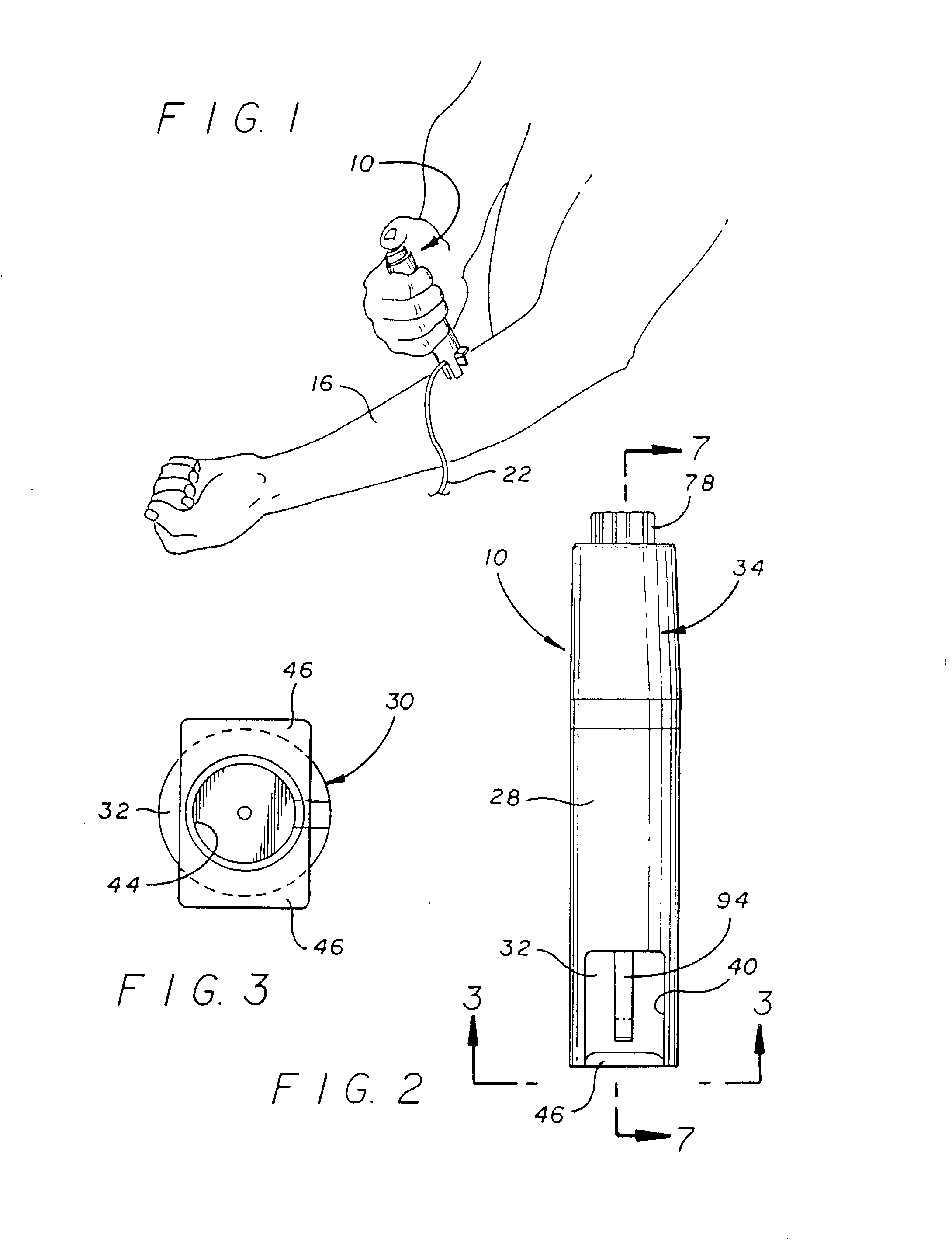
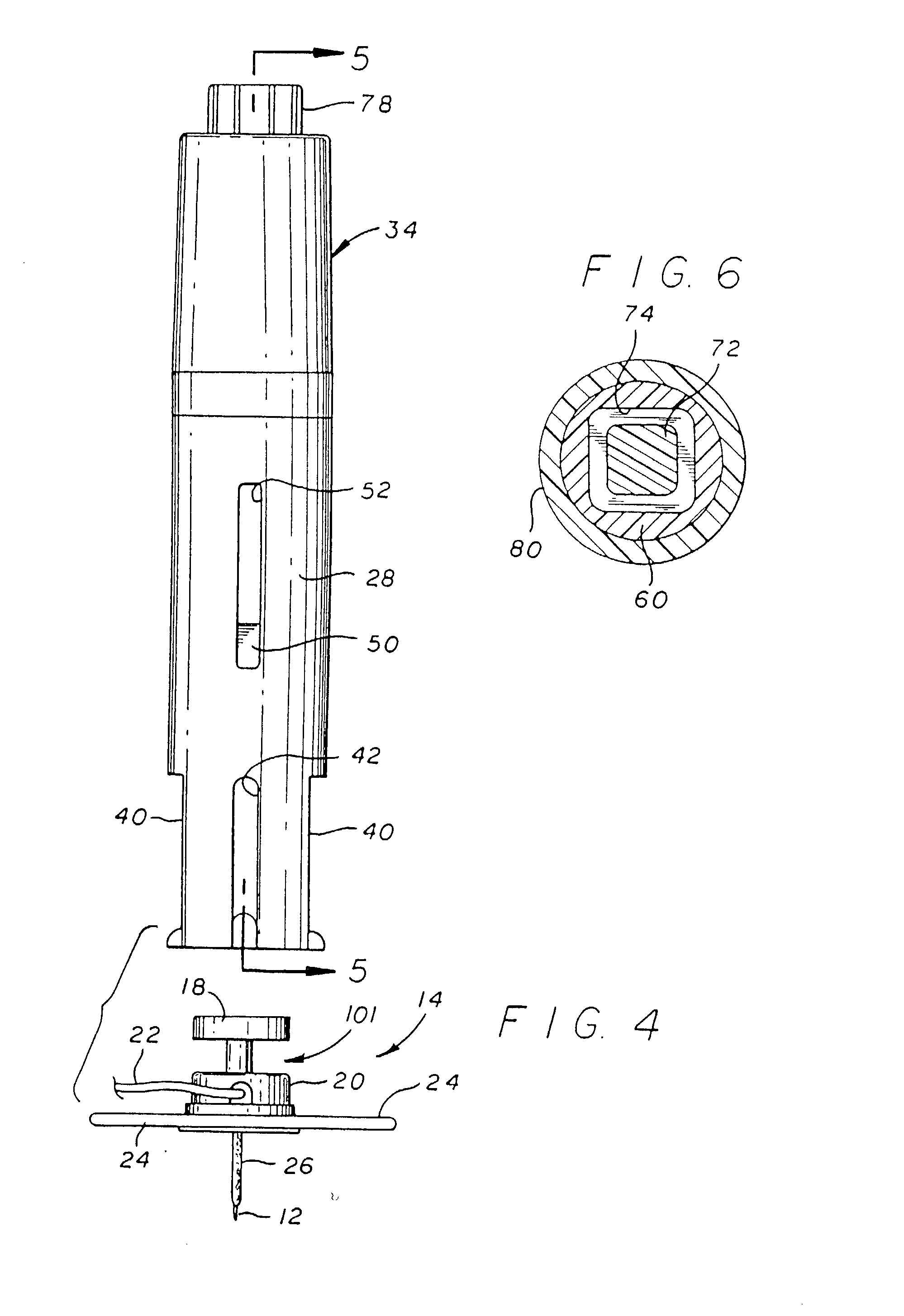
[0107] As shown in the exemplary drawings, an injector (or insertion device) in accordance with the present invention is referred to generally by the reference numeral 10 is provided for quick and easy transcutaneous placement of a medical needle, particularly such as an insertion needle 12 of the type provided with a subcutaneous insertion set 14 as depicted in FIGS. 4 and 7. The injector 10 includes a trigger-type actuator mechanism for transcutaneous placement of the insertion needle 12 with a controlled speed and force, and with the insertion needle 12 oriented at a desired angular position relative to the skin 16 (FIGS. 1 and 9) of the patient.

[0108] The automatic injector 10 of the present invention, as shown in the illustrative drawings, is particularly designed for placement of the insertion needle 12 of a subcutaneous insertion set 14, such as an insertion set of the general type shown and described in U.S. Pat. Nos. 4,755,173; 5,176,662; and 5,257,980, which are incorporat...

second embodiment

[0134]FIGS. 35-40g illustrate an insertion device 500 in accordance with the present invention. The insertion device 500 includes a barrel 502 (or device housing) having a surface seat 501 and an assembly port 503, a carrier body 504 (or plunger or the like) having an assembly rim 505 and a seating flange 506, a drive spring 507 (or driver), a release button 508, and dual spring triggers 510 and 512. As shown in FIG. 35, the barrel 502 performs as a housing to hold the carrier body 504. The carrier body 504 is connected to the barrel 502 by the carrier body being inserted through an opening in the surface seat 501 of the barrel 502, and then passing the assembly rim 505 of the carrier body 504 through the assembly port 503 of the barrel 502. The section of the carrier body 504 with the assembly rim 505 compresses slightly, as it passes through the assembly port 503, due to the presence of compression slots 509, and then essentially restores to its original shape to prevent the carri...

third embodiment

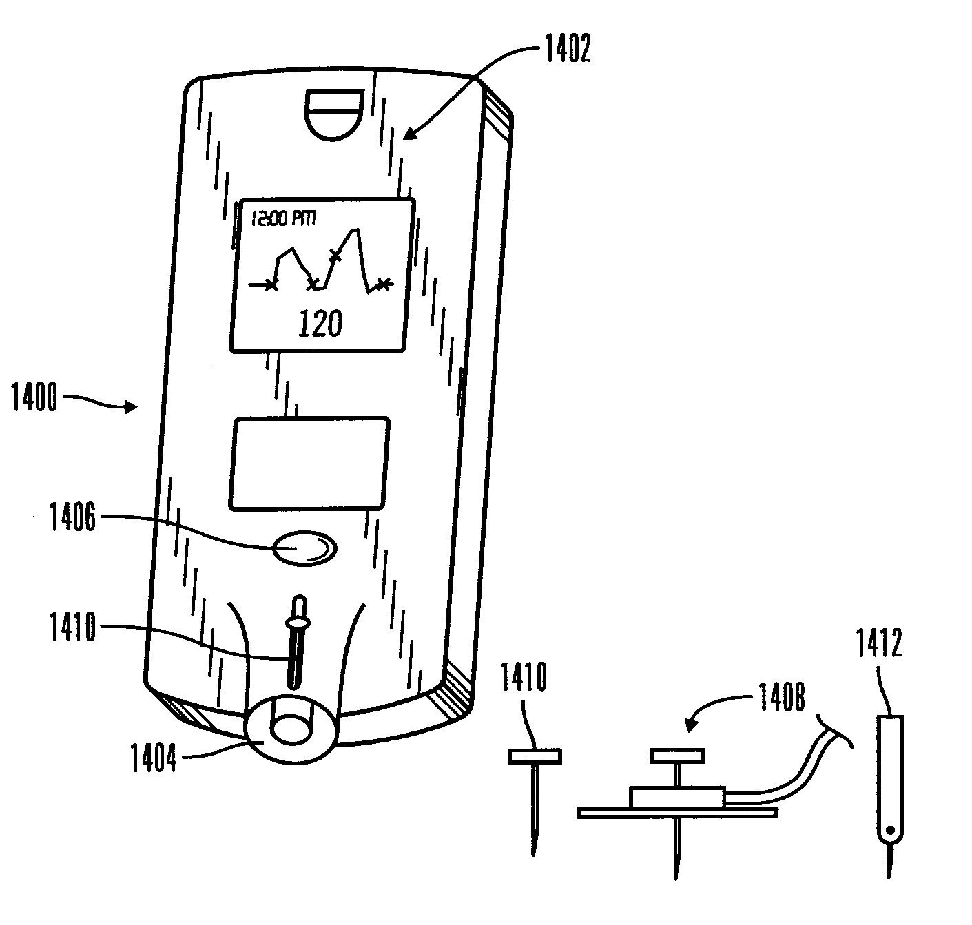
[0143]FIGS. 41-46 illustrate an insertion device 600 in accordance with a third embodiment that is similar to the insertion devices shown in FIGS. 1-34. The insertion device 600 includes a device housing end 601 and a carrier body 602 that has angled insertion contact surfaces 603 and 604. The angled insertion contact surfaces 603 and 604 enable the user to properly angle the insertion device 600 to insert an insertion set 700, or the like, at the proper insertion angle relative to the skin. An insertion set similar to the insertion set 700 is disclosed in U.S. patent application Ser. No. 08 / 871,831 (PCT application Ser. No. US98 / 10832) to Van Antwerp et al. entitled “Disposable Sensor Insertion Assembly” or an insertion set that can be inserted at an angle as disclosed in U.S. patent application Ser. No. 09 / 034,626 to Funderburk et al. entitled “Medication Infusion Set”, both of which are herein incorporated by reference. Preferred embodiments of the insertion device 600 have angle...


PUM


Abstract

An insertion device and insertion set. The insertion device for inserting at least a portion of at least one piercing member of an insertion set through the skin of a patient includes a device housing, a carrier body and a driver. The carrier body is slidably received within the device housing for movement between an advanced position and a retracted position. The carrier body also includes a receiving structure to support the insertion set in a position with the at least one piercing member oriented for insertion through the skin of the patient at a predetermined or variable angle relative to the skin of the patient upon movement of the carrier body from the retracted position to the advanced position. The driver is operatively coupled between the device housing and the carrier body to urge the carrier body from the retracted position toward the advanced position to place at least a portion of the at least one piercing member of the insertion set thorough the skin of the patient to install the insertion set to the patient. The receiving structure of the carrier body is removable from the insertion set while maintaining the installation of the insertion set to the patient.

Description

RELATED APPLICATIONS [0001] This application is a continuation-in-part of U.S. patent application Ser. No. 09 / 839,052, filed Apr. 20, 2001, which is a continuation-in-part of U.S. patent application Ser. No. 09 / 215,356, filed Dec. 18,1998, which is a continuation-in-part of U.S. patent application Ser. No. 09 / 002,303, filed Dec. 31, 1997, both or which are herein specifically incorporated by reference.FIELD OF THE INVENTION [0002] This invention relates generally to an insertion device for automatic placement of an insertion set through the skin of a patient, and in particular embodiments to a compact and easily operated insertion device for placement of an insertion needle of a subcutaneous insertion set or the like through the skin of a patient with a controlled force and insertion speed by the patient. BACKGROUND OF THE INVENTION [0003] Medical needles are widely used in the course of patient care and treatment, particularly with respect to the delivery of selected medications to...

Claims


Application Information

Patent Timeline
Patent Type & Authority Applications(United States)
IPC IPC(8): A61M5/20A61B5/151A61M5/00A61M5/158A61M5/32
CPCA61M5/158A61M2005/1581A61M2005/1583A61M2005/1585A61M2005/3249
Inventor KOVELMAN, PAUL H.SAFABASH, JASON H.MCCONNELL, SUSAN M.MARANO, APRIL A.HOUGHTON, FREDERICK C.
Owner MEDTRONIC MIMIMED INC
Why Eureka
Try Eureka