Modular staircase kit

a modular and staircase technology, applied in the direction of treads, manufacturing tools, constructions, etc., can solve the problems of increasing labor intensity, increasing construction costs, and increasing the cost of curved staircases, so as to reduce the overall construction cost and assembly time

Inactive Publication Date: 2007-06-28
ARCH RITE
View PDF10 Cites 19 Cited by
  • Summary
  • Abstract
  • Description
  • Claims
  • Application Information

AI Technical Summary

Benefits of technology

[0010] The present invention specifically addresses the above referenced needs associated with curved staircases. More specifically, the present invention is a uniquely configured staircase kit that may be prefabricated at an offsite location such as a factory. The staircase kit may be later assembled at a job site to form a staircase that may be attached to a bui...

Problems solved by technology

Unfortunately, prior art curved staircases are generally more expensive than straight staircases.
Such increased expense is due in large part to the cost of forming the curved portions of the curved staircase.
Furthermore, the installation of a curved staircase requires a higher degree of skill and is sometimes comparable to the high level of skill required in cabinet making.
The increased expense is also due in part to the time consuming manner in which such curved staircases are installed.
As may be appreciated, such conventional method for curved staircase construction is extremely time-consuming.
Furthermore, such conventional building method is highly dependent upon skilled labor and the availability of specialized tooling in order to produce a staircase that meets precise tolerance requirements mandated by local and national building codes.
Unfortunately, due to the difficulty in controlling the tolerances of the building structure to which the completed staircase is to be connected, problems ...

Method used


Image

  • Modular staircase kit
  • Modular staircase kit
  • Modular staircase kit

Examples


Embodiment Construction

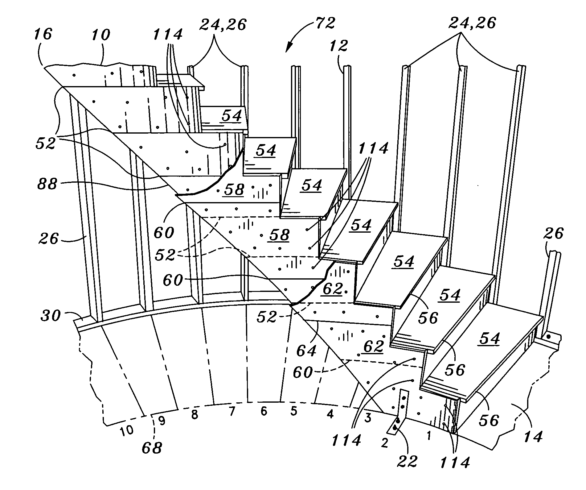
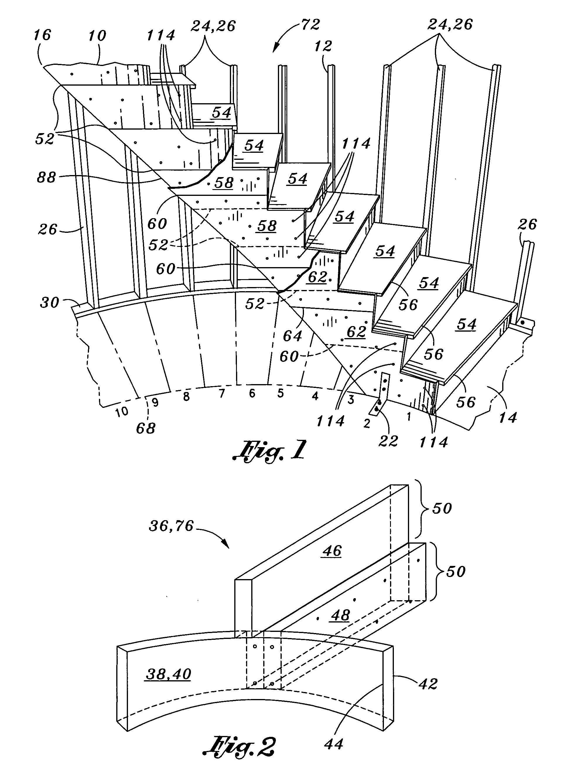
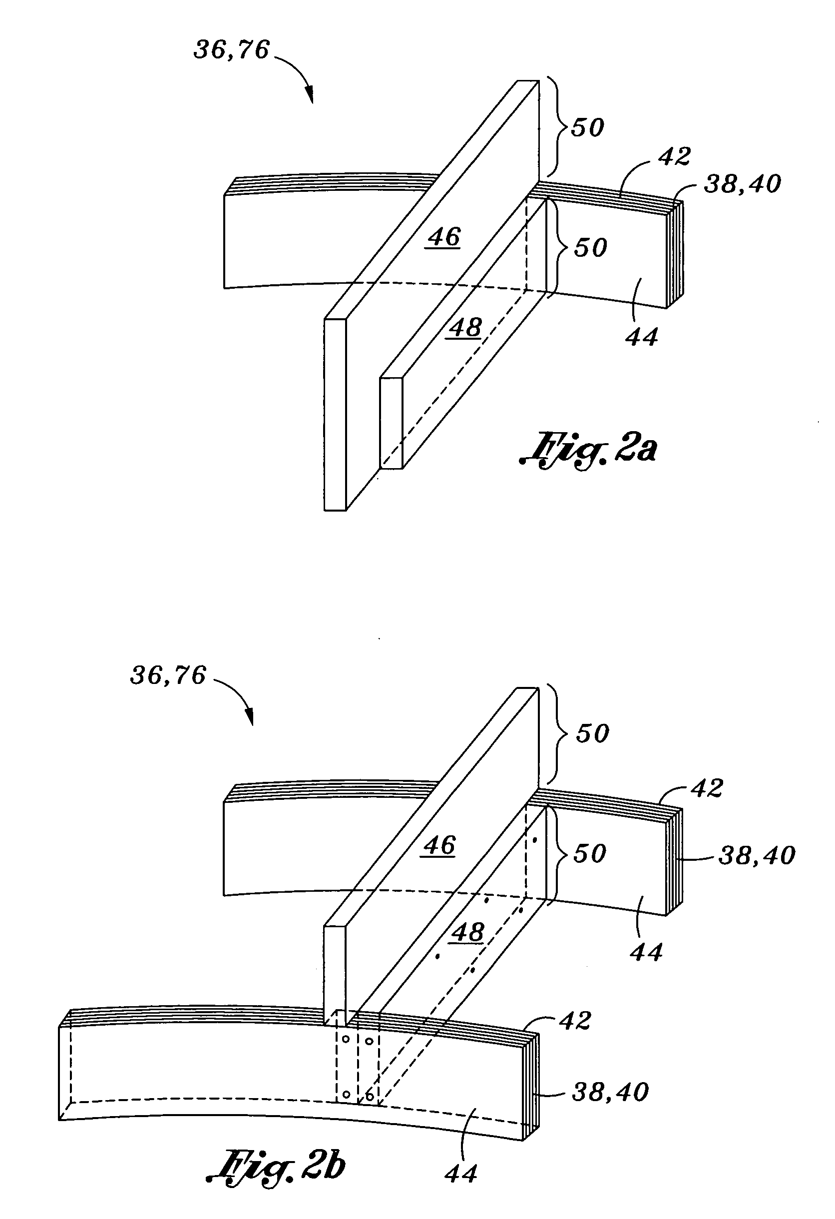
[0037] Referring now to the drawings wherein the showings are for purposes of illustrating the present invention and not for purposes of limiting the same, shown in FIGS. 1-6a is a staircase 10 which is constructed of pre-manufactured step modules 36 and which may be configured to form a straight or a curved staircase 10 or any combination thereof. However, for purposes of this discussion, the staircase will be described with reference to a curved staircase 10. Shown in FIGS. 7-13 is a tooling fixture 92 for pre-manufacturing a staircase kit such as may be pre-fabricated on the tooling fixture 92 and disassembled for later installation at a job site to form the curved staircase 10.

[0038] As can be seen in FIGS. 1 and 6, the step modules 36 may be assembled in stacked arrangement on top of one another. The staircase 10 may be provided in an “entirely free-standing”74 version wherein the curved staircase 10 is not connected to the building structure 12. In this regard, the entirely f...


PUM


Abstract

A staircase kit comprises a plurality of side panels and a plurality of inner and outer reinforcing panels disposed in layered arrangement over the side panels. The side panels and inner and outer reinforcing panels have preformed holes extending axially therethrough. The side panels are disposed in stacked relation to one another to form a plurality of module joints there between. Likewise, the inner reinforcing panels are disposable in overlapping relationship to the module joints. The inner reinforcing panels form a plurality of inner panel joints that are preferably disposed in staggered relationship to the module joints. The outer reinforcing panels are disposed in overlapping relationship to the inner panel joints to form a plurality of outer panel joints that are disposed in staggered relationship to the inner panel joints. The preformed holes of the side panels are axially alignable with the preformed holes of the inner and outer reinforcing panels such that mechanical fasteners may be installed at the job site in order to assemble the staircase kit for interconnection to a building structure.

Description

CROSS-REFERENCE TO RELATED APPLICATIONS [0001] This is a continuation-in-part application of pending U.S. patent application Ser. No. 11 / 189,580 entitled MODULAR CURVILINEAR STAIRCASE and filed on Jul. 26, 2005, and is related to continuation-in-part U.S. patent application Ser. No. 11 / 273,206 also entitled MODULAR CURVILINEAR STAIRCASE filed on Nov. 14, 2005, the entire contents of both applications being expressly incorporated by reference herein.STATEMENT RE: FEDERALLY SPONSORED RESEARCH / DEVELOPMENT [0002] (Not Applicable) BACKGROUND OF THE INVENTION [0003] The present invention relates generally to building construction and, more particularly, to a uniquely configured modular staircase kit that is comprised of individual step modules that are pre-manufactured offsite using a specialized tooling fixture. The step modules are then assembled in stacked arrangement at a job site to form a staircase which may also be interconnected to a building structure such as a home. [0004] In bu...

Claims


Application Information

Patent Timeline
IPC IPC(8): E04F11/00E04F19/10
CPCB27M3/12E04F11/035E04F11/108
Inventor BARRY, MICHAEL A.GOODWIN, GEORGE E.
Owner ARCH RITE
Why Eureka
Try Eureka