Image forming apparatus and control method therefor

a technology of image forming apparatus and control method, which is applied in the direction of recording apparatus, instruments, electrographic process, etc., can solve the problems of reducing the productivity of the image forming apparatus, unable to obtain unable to achieve the output of image formation, etc., to suppress the reduction in productivity and excellent images

Inactive Publication Date: 2007-06-28
CANON KK
View PDF2 Cites 4 Cited by
  • Summary
  • Abstract
  • Description
  • Claims
  • Application Information

AI Technical Summary

Benefits of technology

[0021] It is a first object of the present invention to provide an image forming apparatus which is capable of forming an excellent image while suppressing reduction in productivity to a minimum even when an abnormality occurs in detection of an HP mark on an intermediate transfer member, and a control method therefor.

Problems solved by technology

In the above described abnormality-detecting method, however, when an abnormality is detected, it is required to stop the operation of the image forming apparatus and carry out maintenance operation, such as HP mark cleaning or replacement of the intermediate transfer member, and hence image forming operation cannot be carried out until completion of the maintenance operation, which leads to considerable reduction of productivity of the image forming apparatus.
Further, when one of the HP marks becomes abnormal, one page of an image is formed based on detection of the normal HP mark, but the other page of an image is not formed, causing degradation in productivity.
Moreover, when the two marks become abnormal, the image forming apparatus is stopped so that image formation output cannot be obtained.
This is inconvenient to users when they are in haste to obtain image formation output, e.g. when it is required to output a small number of copies urgently.
On the other hand, one of factors causing reduction of productivity is that it takes a longer time period to detect a first HP mark depending on the position where the intermediate transfer member has been stopped.
This consequence is inconvenient when users are in haste to obtain image formation output, e.g. when it is required to print a small number of copies urgently.
However, since tension is applied to the intermediate transfer belt stretched around a plurality of rollers, if the intermediate transfer belt is constantly stopped in the same position, deformations in portions of the belt in contact with the respective rollers, i.e. so-called permanent deformations occur, which can cause degradation of the intermediate transfer belt and considerably lower image quality.
However, with this arrangement, it is required, in actuality, to mark numerous HP marks on the intermediate transfer belt so as to detect an HP mark in a minimum wait time while preventing permanent deformation of the intermediate transfer belt, which causes an increase in manufacturing costs.
As described above, in an intermediate transfer type image forming apparatus in which colors are superimposed based on HP mark detection, it is difficult to constantly stop an intermediate transfer belt in the same position upon termination of an image forming process, which causes variation in a time period from a time point when the intermediate transfer belt in stoppage is driven to a time point when an HP mark is detected by a sensor for the first time.
Further, to solve this problem, it is necessary to arrange timers, for example, which causes an increase in manufacturing costs.
Thus, the time period before the first-time HP mark detection occupies a large portion of a time period required for the entire image forming operation, which is generally inefficient for users who very often uses a job for printing a small number of sheets per one image forming operation.
If, however, the HP mark detection cannot be carried out, it is no longer possible to detect the circumferential length of the intermediate transfer belt, making it impossible to carry out the image formation based on HP mark detection.
As a result, the image forming apparatus stops operating, and an image formation output cannot be obtained.
This causes inconveniences for users who are in haste to obtain image formation output.

Method used


Image

  • Image forming apparatus and control method therefor
  • Image forming apparatus and control method therefor
  • Image forming apparatus and control method therefor

Examples


first embodiment

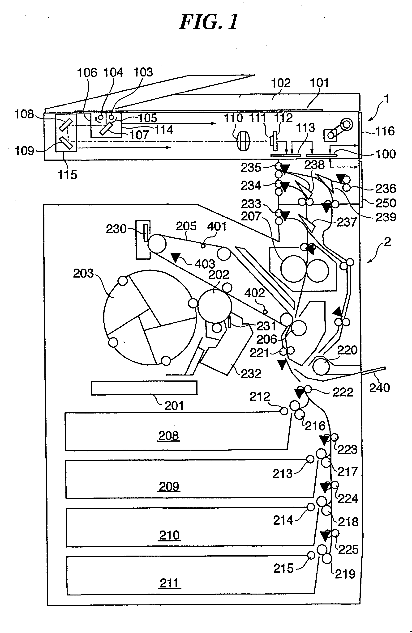
[0063]FIG. 1 is a schematic cross-sectional view of an image forming apparatus according to the present invention. This image forming apparatus functions as a full-color image forming apparatus, and is comprised of a color reader section 1 and a color printer section 2.

[0064] First, a description will be given of the color reader section 1. On an original platen glass 101 of the color reader section 1, there is mounted an automatic original feeder (ADF) 102 that automatically feeds originals onto the original platen glass 101. It should be noted that the image forming apparatus may be provided with a mirror pressure plate, not shown, or a white pressure plate, not shown, in place of the automatic original feeder 102. A carriage 114 accommodates light sources 103 and 104, reflectors 105 and 106, and a mirror 107. The light sources 103 and 104 are implemented by halogen lamps, fluorescent lamps, xenon lamps, or the like, and illuminate an original on the original platen glass 101.

[00...

second embodiment

[0125] In the following, a description will be given of an image forming apparatus according to the present invention.

[0126] The apparatus according to the present embodiment is basically identical to the image forming apparatus according to the first embodiment, and hence only different points will be described.

[0127] As distinct from the first embodiment in which the mark sensors 403 and 404 dedicated to the respective individual detections of the first and second HP marks 401 and 402 marked in the intermediate transfer member 205 are provided, as shown in FIG. 4, in the second embodiment, only a single mark sensor 1103 common to first and second HP marks 1101 and 1102 is provided in the intermediate transfer member 205 as shown in FIG. 11.

[0128] Similarly to the first and second HP marks 401 and 402 in the first embodiment, the first HP mark 1101 and the second HP mark 1102 are marked in the intermediate transfer member 205 in a manner separated from each other by half the circ...


PUM

PropertyMeasurementUnit
distanceaaaaaaaaaa
circumferenceaaaaaaaaaa
longitudinal lengthaaaaaaaaaa

Abstract

An image forming apparatus which is capable of forming an excellent image while suppressing reduction in productivity to a minimum even when an abnormality occurs in detection of an HP mark on an intermediate transfer member. When there occurs abnormality in detection of any of HP marks, an alternate signal is generated in place of a signal associated with a mark the detection of which is determined to be abnormal, and image formation is carried out with reference to the time of normal HP mark detection and the alternate signal.

Description

BACKGROUND OF THE INVENTION [0001] 1. Field of the Invention [0002] The present invention relates to an image forming apparatus and a control method therefor, and more particularly to a technique of controlling image formation timing in image formation performed using an intermediate transfer member. [0003] 2. Description of the Related Art [0004] Conventionally, image forming apparatuses, such as copying machines and printers, utilizing electrophotography include ones which perform image formation using a belt-like intermediate transfer member (hereinafter referred to as “the intermediate transfer belt”). In general, in an image forming apparatus of this type, electrostatic latent images formed on respective photosensitive members are developed by toner to be visualized, and the toner images are transferred onto the intermediate transfer belt, followed by being collectively transferred onto a recording material (such as a sheet). This transfer method is generally called the interme...

Claims


Application Information

Patent Timeline
Patent Type & Authority Applications(United States)
IPC IPC(8): B41D7/00
CPCG03G15/0152G03G15/0173G03G15/0121G03G2215/0158
Inventor TAKATA, SHINICHISAKAI, AKIHIKOKAWAMURA, TAKUYAMAEDA, YUICHIRO
Owner CANON KK
Why Eureka
Try Eureka