Cascade unit for a heating system with two or more heating boilers

a heating system and boiler technology, applied in the direction of machines/engines, lighting and heating apparatus, heating types, etc., can solve the problems of large assembly expenditure, inability to carry associated boilers, and inability to carry cascade units, etc., to achieve extensive and thus cost-saving prefabrication, reduce assembly expenditure, and smooth transportation

Active Publication Date: 2007-06-28
COMFORT SINUSVERTEILER
View PDF9 Cites 12 Cited by
  • Summary
  • Abstract
  • Description
  • Claims
  • Application Information

AI Technical Summary

Benefits of technology

[0004] For this invention, the problem accordingly presents itself of creating a cascade unit of the initially mentioned type which avoids the presented disadvantages and which achieves, in particular, a significant reduction of the assembly expenditure in the installation of a heating system and which enables an extensive and thus cost-saving prefabrication as well as a smooth transport.

Problems solved by technology

By means of these feet or brackets, the cascade unit can, for itself, be mounted with sufficient stability; however, this known cascade unit is not able to carry the associated boilers because the boilers on the one hand and the cascade unit on the other hand are connected with each other only via the boiler inlet flow connections and the boiler return flow connections.
The boiler inlet flow connections and the boiler return flow connections are, however, not suitable for taking up the great weight of the boilers.
With this known state of the art, it is considered disadvantageous that, for the heating installation, major assembly expenditures are required on location in the heating room and that, additionally, very precise workmanship is absolutely required so that the heating boilers on the one hand provided on the wall or on the ceiling and the cascade unit also mounted in the heating room with its own feet or brackets will be positioned correctly to each other.
Experience has shown that this presents a source of errors, resulting in frequently expensive adjustment work or modifications being required when the cascade unit is hydraulically connected with the boilers.

Method used


Image

  • Cascade unit for a heating system with two or more heating boilers
  • Cascade unit for a heating system with two or more heating boilers
  • Cascade unit for a heating system with two or more heating boilers

Examples


Embodiment Construction

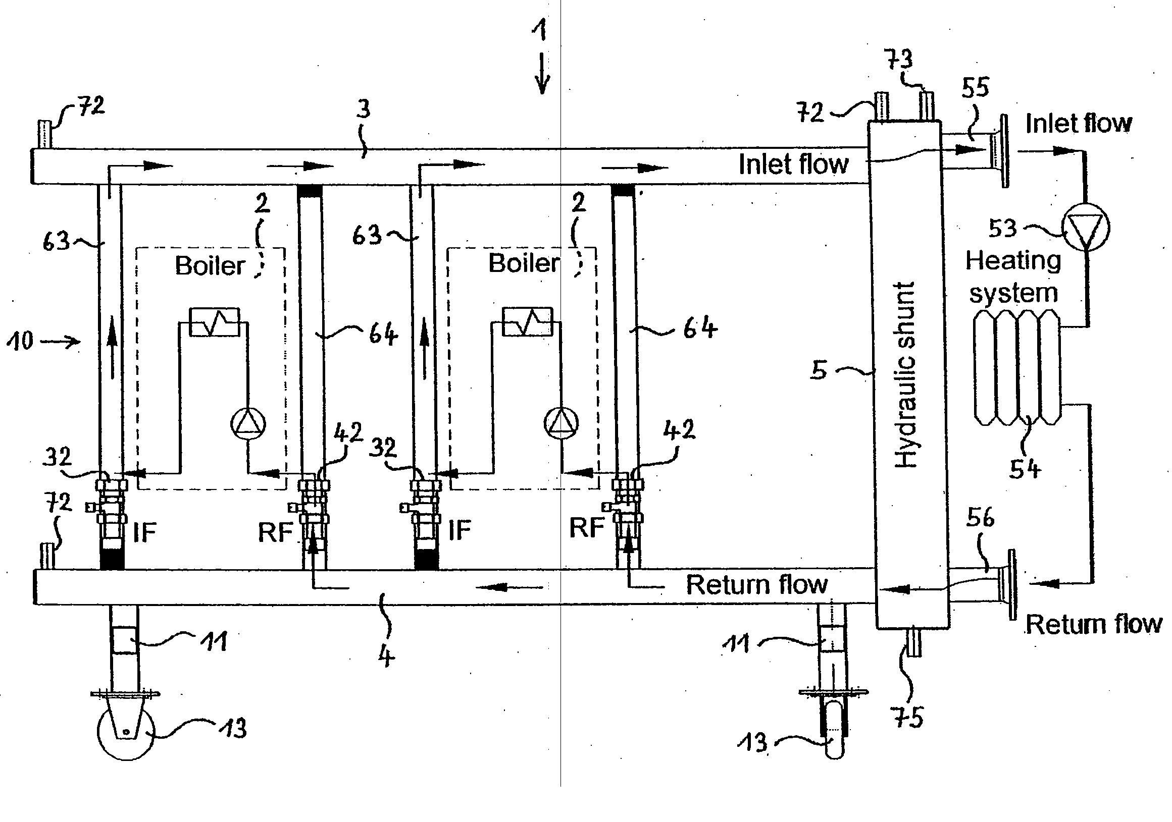
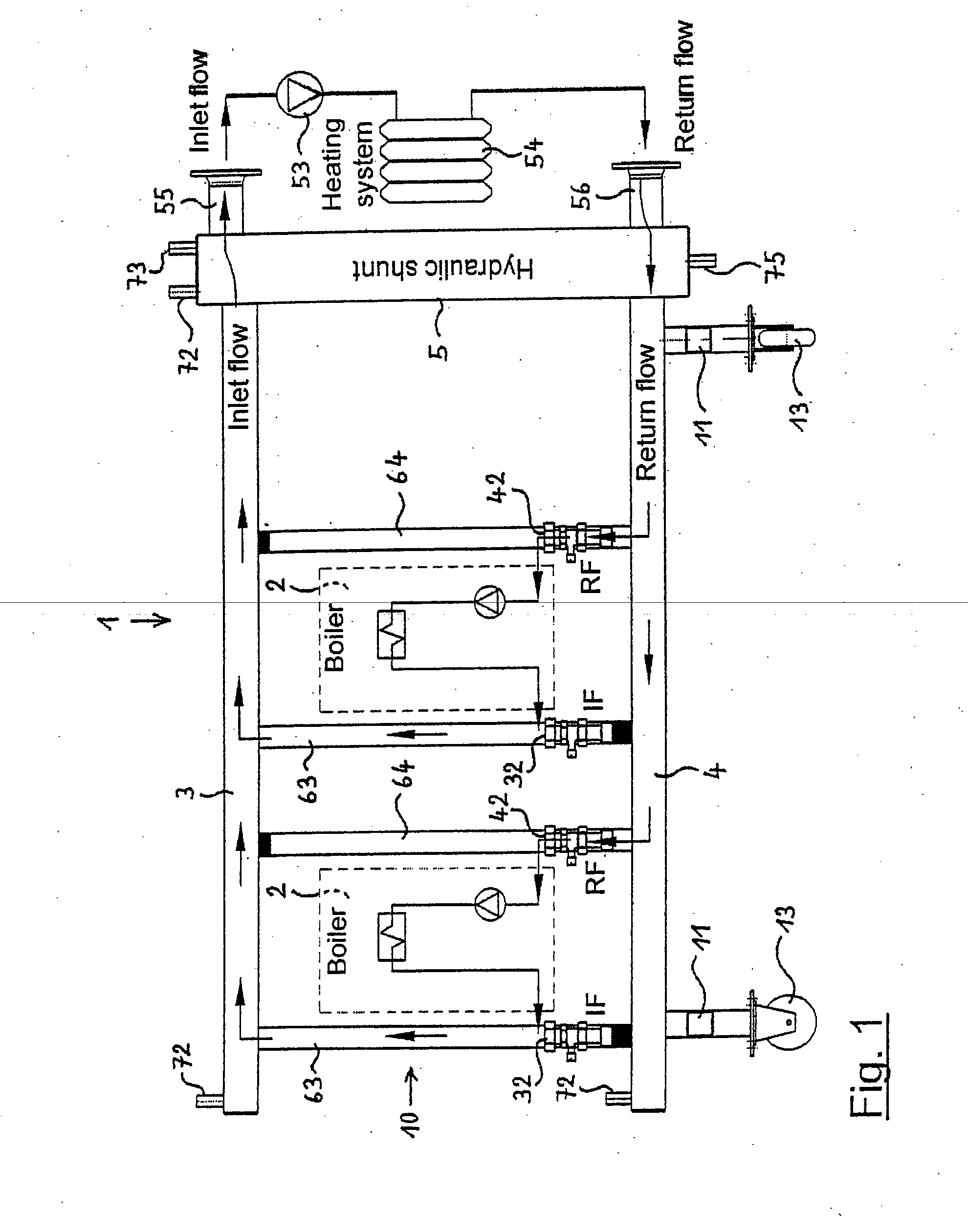
[0041] In the example of the cascade unit 1 according to FIG. 1, it is designed for taking up two heating boilers 2. For this, the cascade unit 1 comprises on the top a horizontally extending boiler inlet flow header 3 and at a vertical distance thereunder an also horizontally extending boiler return flow manifold 4. In vertical direction, the header 3 and the manifold 4 are mechanically connected with each other through vertical pipe sections 63 and 64. Here, alternately, a vertical pipe section 63 is hydraulically connected with the header 3 and a pipe section 64 with the manifold 4. That means that the pipe sections 63 are impervious to liquids at their bottom end and are here only mechanically connected with the manifold 4, not however hydraulically. Correspondingly, the vertical pipe sections 64 are connected at their upper end only mechanically with the header 3, not however hydraulically.

[0042] At their right face end in FIG. 1, the header 3 and the manifold 4 are connected ...


PUM


Abstract

The invention relates to a cascade unit for a heating system with two or more heating boilers, in particular condensing boilers, with a hydraulic shunt which is connected on the one hand with the inlet flows and return flows of all heating boilers and on the other hand with at least one heating circuit inlet flow and heating circuit return flow each, with the cascade unit furthermore comprising one each of the essentially horizontally extending boiler inlet flow header and boiler return flow manifold, the header and the manifold being connected with the hydraulic shunt, and the header and the manifold each being designed with prepared connecting nozzles fittingly placed for a group of two or more heating boilers the connection of the heating boiler inlet flows and the heating boiler return flows. The cascade unit forms at least one self-supporting support frame on which at least one of the heating boilers is mountable.

Description

BACKGROUND OF THE INVENTION [0001] This invention relates to a cascade unit for a heating system with two or more heating boilers, in particular condensing boilers, with a hydraulic shunt which is connected on the one hand with the inlet flows and return flows of all heating boilers and on the other hand with at least one heating circuit inlet flow and heating circuit return flow each, with the cascade unit furthermore comprising one each of the essentially horizontally extending boiler inlet flow header and boiler return flow manifold, the header and the manifold being connected with the hydraulic shunt, and the header and the manifold each being designed with prepared connecting nozzles fittingly placed for a group of two or more heating boilers for the connection of the heating boiler inlet flows and the heating boiler return flows. [0002] A cascade unit of the aforementioned type is known from DE 202 11 303 U1. This known cascade unit can be provided with feet placeable on a flo...

Claims


Application Information

Patent Timeline
Patent Type & Authority Applications(United States)
IPC IPC(8): F22B37/24
CPCF24D3/1066F24D3/1091F24D12/02F24D2200/043F24H9/0094Y02B30/14Y10T137/85938Y02B30/00
Inventor MUKOMILOW, DARIUSZ
Owner COMFORT SINUSVERTEILER
Why Eureka
Try Eureka