
Door glass assembly with powered blind

a technology of door glass and powered blinds, applied in the direction of door/window protective devices, wing arrangements, curtain suspension devices, etc., can solve the problems of difficult incorporation of powered blinds into insulated glass, particularly challenging, etc., and achieve the effect of enhancing the life of powered blinds and preventing motor burnou

Inactive Publication Date: 2007-06-28
ODL
View PDF37 Cites 24 Cited by
  • Summary
  • Abstract
  • Description
  • Claims
  • Application Information

AI Technical Summary

Benefits of technology

[0004] The aforementioned problems are overcome in the present invention in which a door glass or other window assembly includes an improved powered blind having a clutch between the electric motor and the blind. The clutch permits the motor to continue rotating even after a physical limit or stop on the blind is reached. This construction prevents motor burn out and therefore enhances the life of the powered blind. The door glass assembly includes a pair of frame halves and a power pack secured between the frame halves. The power pack is secured to only one of the two frame halves. Consequently, the frame halves may be separated without fear of the power pack coming loose and / or falling out of the assembly. In a preferred aspect, the one frame half includes a battery compartment door to permit access to replaceable batteries in the battery pack. The invention has applicability beyond the disclosed powered blinds and can be used in conjunction with any electrically powered device or option in a door glass or other window assembly.

Problems solved by technology

However, the incorporation of a powered blind into insulated glass presents a challenge.
This is particularly challenging in the environment of door glass and other window assemblies where electrical power typically is not readily available.

Method used


Image

  • Door glass assembly with powered blind
  • Door glass assembly with powered blind
  • Door glass assembly with powered blind

Examples


Embodiment Construction

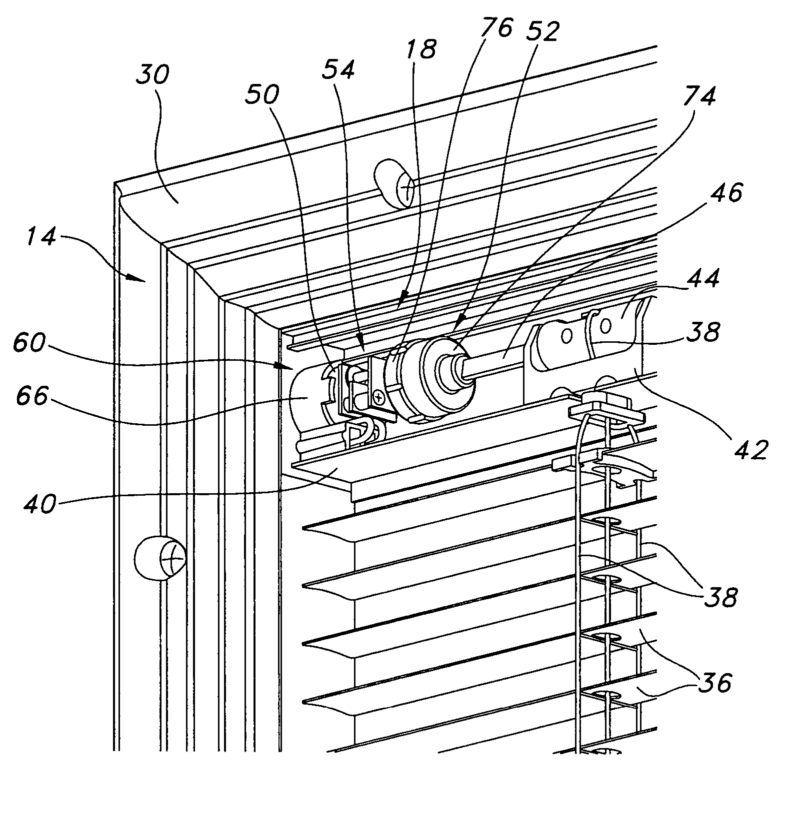
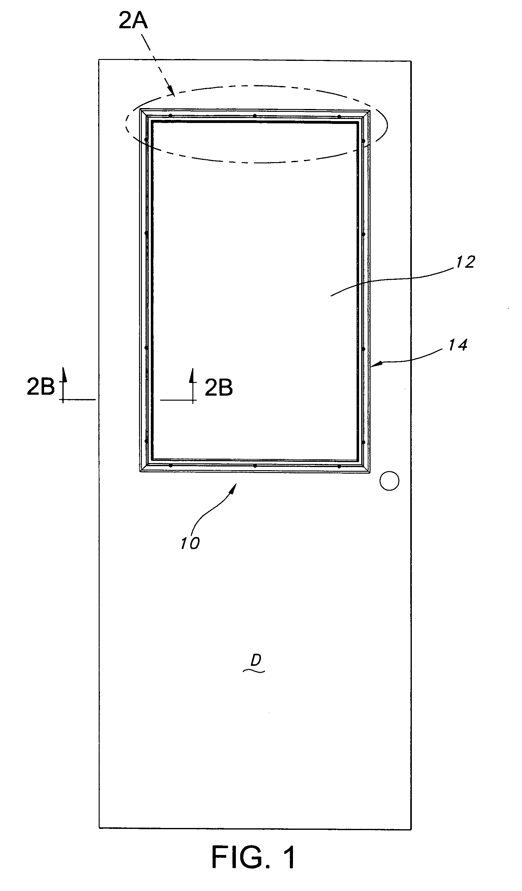
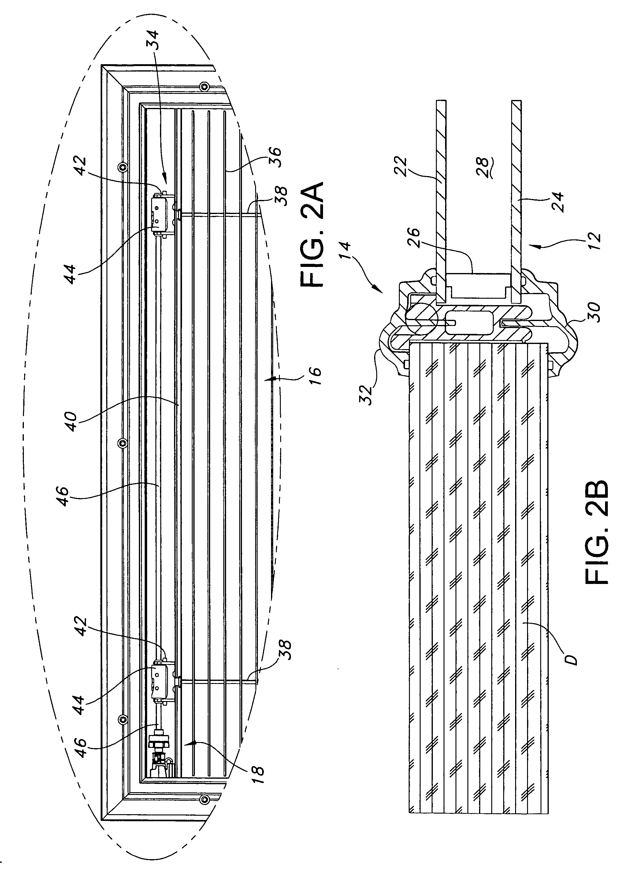
[0015] A door glass assembly constructed in accordance with a preferred embodiment of the invention is illustrated in the drawings and generally designated 10. The assembly 10 includes a door glass 12, a frame 14, a blind 16, a drive mechanism 18, and a power pack 20. The drive mechanism 18 is powered by the power pack assembly 20 to operate the blind 16.

[0016] The door glass 12 is generally well-known to those skilled in the art. The door glass 12 includes a pair of glass panels 22 and 24 connected to and separated by a spacer frame 26. The panels are hermetically sealed to the spacer frame 26. An enclosed space 28 is defined between the glass panels 22 and 24.

[0017] The frame 14 is also generally known to those skilled in the art. The frame 14 includes an inner frame half 30 and an outer frame half 32. The two frame halves are intersecured using screws or other well-known techniques to support the door glass 12 within a door D.

[0018] The frame 14 also includes several features ...


PUM


Abstract

A self-contained, electrically powered door glass unit including a glass assembly, a window covering within the glass assembly, an electric motor driving the window covering, a battery pack powering the motor, and a frame adapted to support the unit within a door. The frame includes first and second frame halves, and the battery pack is supported by only one of the frame halves.

Description

BACKGROUND OF THE INVENTION [0001] The present invention relates to door glass and window assemblies, and more particularly to door glass and window assemblies that include integral blinds. [0002] The incorporation of blinds into door glass and other window assemblies and has gained widespread acceptance. Typically, such assemblies include an insulated glass (IG) defining an enclosed space between two panels. The blind is positioned between the two panels, and actuators are provided outside of the glass to operate the blind (e.g. tilt and / or to raise / lower). [0003] As an option, the blind can be “powered,” including an electric motor. A powered blind can be tilted and / or raised / lowered in response to the actuation of one or more electric switches, or a remote control. However, the incorporation of a powered blind into insulated glass presents a challenge. Specifically, electrical power must be provided to the electric motor. This is particularly challenging in the environment of doo...

Claims


Application Information

Patent Timeline
IPC IPC(8): A47H1/00
CPCE06B3/5892E06B7/30E06B9/264E06B9/32
Inventor HUTCHINGS, DOUGLAS F.HOMER, RICHARD L.DAVIS, LEE W.KROCHMAL, ANDREW R.
Owner ODL
Learn More