Electric wire protective tube and insulating coupler

a protective tube and insulating coupler technology, applied in the direction of insulated conductors, cables, conductors, etc., can solve the problems of large air gap, shock and possibly death, bulky or heavy, etc., and achieve the effect of small size, low weight, and large air gap

Active Publication Date: 2007-06-28
HASTINGS FIBER GLASS PRODS
View PDF11 Cites 0 Cited by
  • Summary
  • Abstract
  • Description
  • Claims
  • Application Information

AI Technical Summary

Benefits of technology

[0010]Yet another aspect of the present invention is that it provides isolation from an energized conductor at high voltages without a protective tube needing to be bulky.
[0011]By making the protective tube out of a lightweight plastic (for example, polyethylene) and using interleaving dielectric leaves to provide a large air gap, a number of advantages accrue. A protective cover embodied according to the present invention has a relatively small size, has low weight, and is easy to store since it is not bulky and takes up less space.
[0012]A coupler is used to join together more than one such protective cover in series. The coupler is of a two piece construction with a first inner insulation barrier that has interleaving dielectric leaves like those of the protective cover. A second outer insulating barrier surrounds the first insulating barrier. The inner insulating barrier has a thinned portion providing a hinge for opening flexibility. The second outer insulating barrier covers the hinged portion of the inner barrier and provides a spring bias to help keep the dielectric leaves of the first barrier joined together in an interleaved relationship.

Problems solved by technology

Such contact would clearly be hazardous causing shock and possibly death.
A problem with the protective covers that are available for use on high voltage conductors is that they are bulky or heavy.
The protective covers made of rubber are quite heavy because of their large size that is dictated by the need for a large air gap.
The protective covers made from other materials may not be as heavy as rubber ones, but they also rely upon a large air gap for insulation, and the large air gap makes the protective covers large and bulky.
In either case, the protective covers are awkward to work with and place over or remove from the electrical conductors.
Additionally, the bulky protective covers pose a storage challenge since they take up so much space when not in use.

Method used


Image

  • Electric wire protective tube and insulating coupler
  • Electric wire protective tube and insulating coupler
  • Electric wire protective tube and insulating coupler

Examples


Embodiment Construction

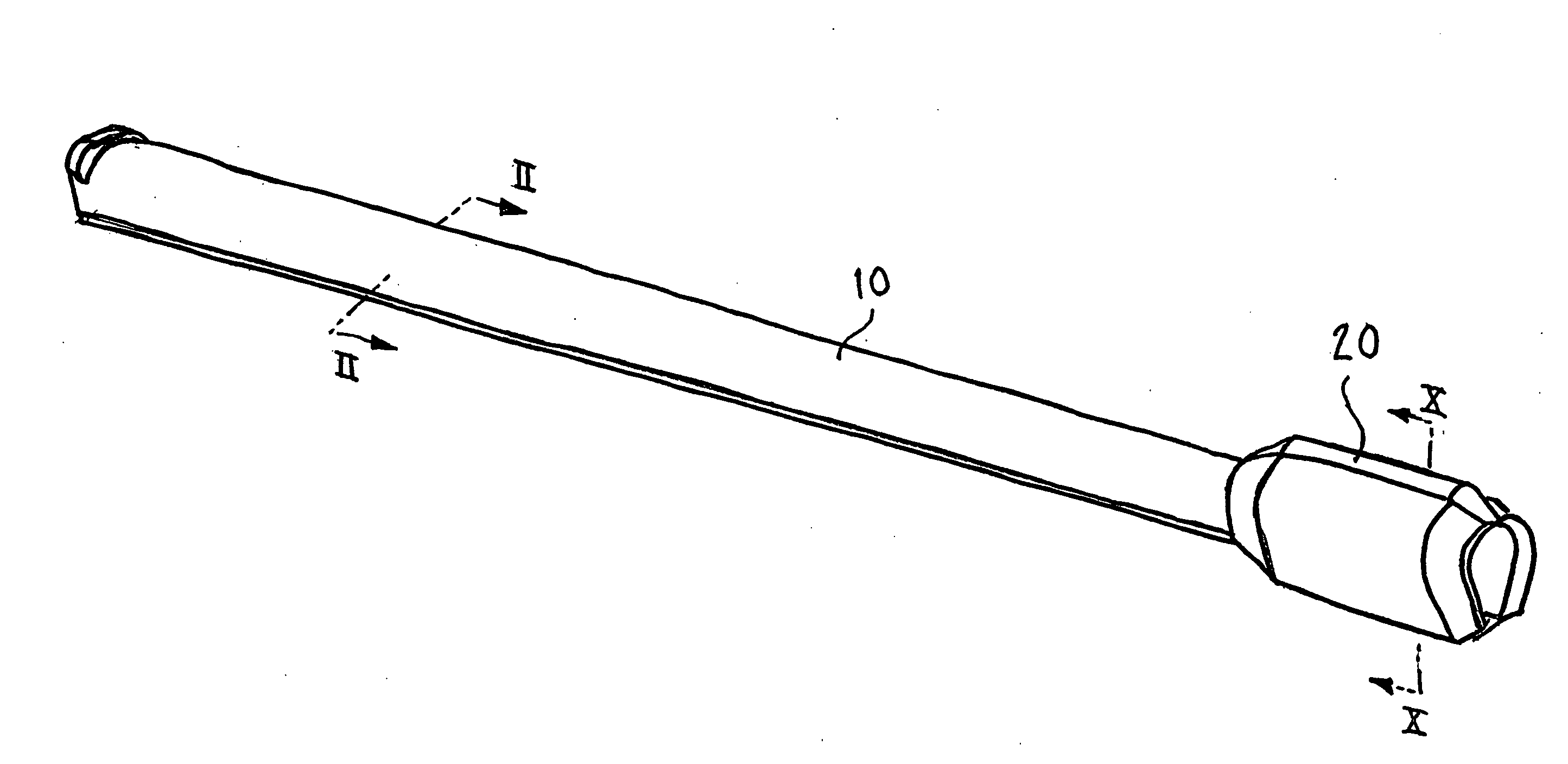
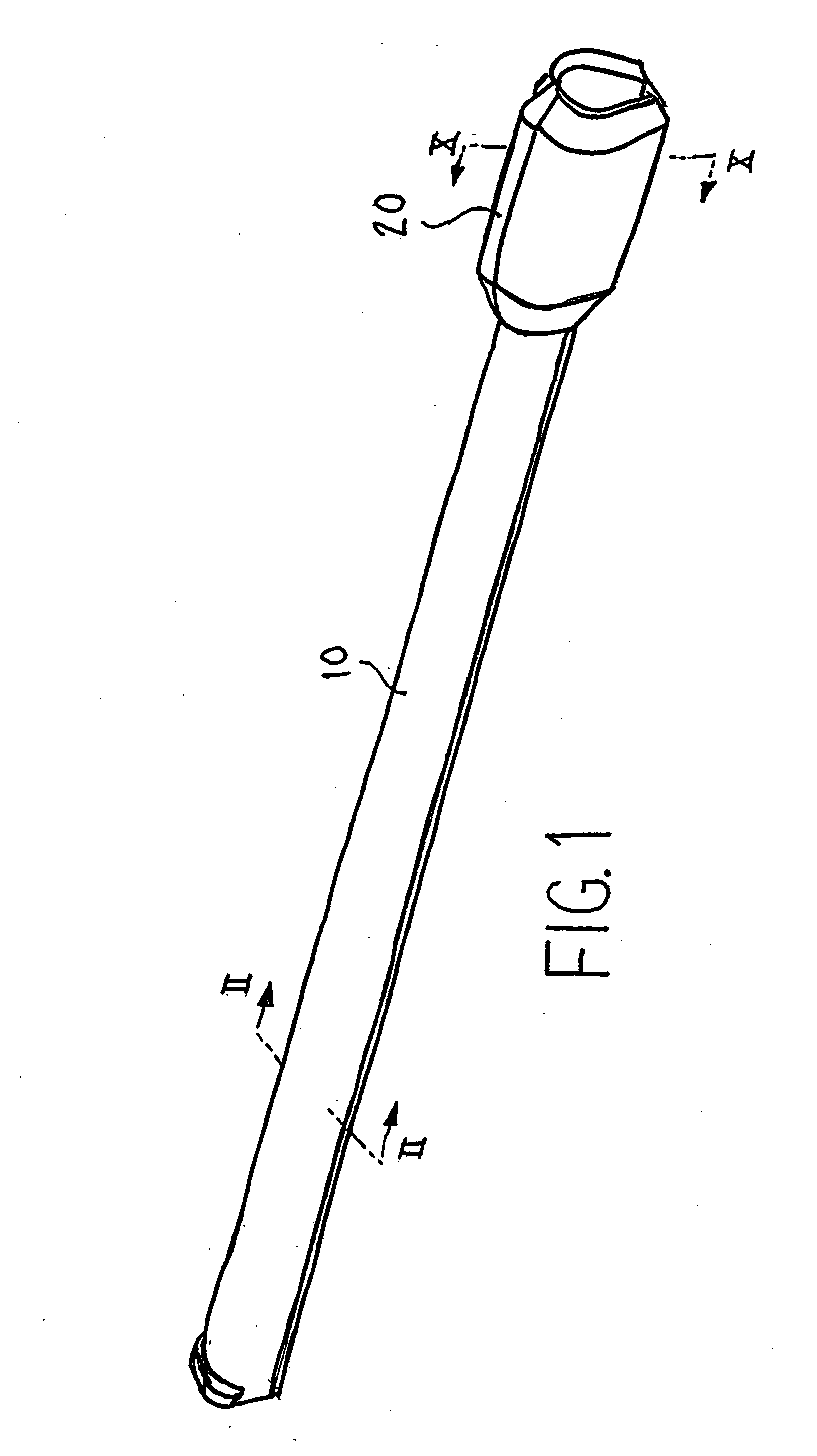
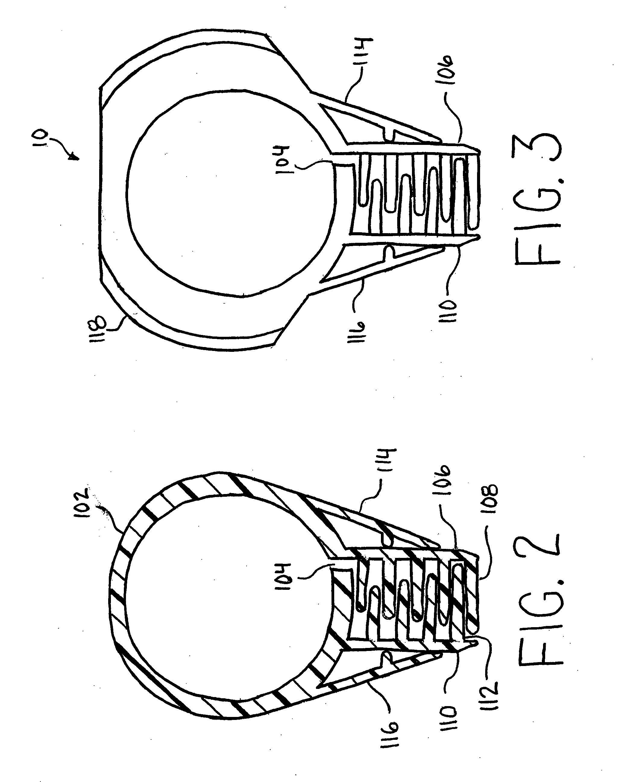
[0024]When it is desired to isolate an energized conductor from possible contact with a worker, the conductor is wrapped within an insulating material. When the conductor is energized at great voltages, the thickness of the insulating material, or the air gap provided by the design of the material, must be of a commensurate large size. Although it is not a challenge to find a material that will insulate an energized conductor at 25 kV, it remains a challenge to provide an air gap of sufficient size. The air gap is useful in order to allow for the cover to be installed over and removed from the electric conductor without removing the electric conductor from its circuit.

[0025]Rather than making the gap larger by making the part larger, as is done in conventional devices, the present invention makes the length of the air gap long by the use of overlapping dielectric leaves, so that the overall size of the protective tube (or “line shield”) could be maintained relatively small. This pro...


PUM


Abstract

A line guard is configured so as to have a very large air gap with a small overall physical size of the device. Opposed interleaved sets of plural insulating leaves are formed along a discontinuity extending along the length of the line guard so as to greatly extend the length of the air gap. This air gap structure allows the overall size of the line guard to be small thus providing advantages of reduced weight, ease of handling, and ease of storage. A two piece coupler apparatus is provided for joining adjacent line guards in a way that is both flexible and provides sufficient dielectric to operate at high voltages in a small package.

Description

CROSS REFERENCE TO RELATED APPLICATIONS[0001]This application claims the benefit of U.S. Provisional Application Ser. No. 60 / 740 343, filed Nov. 29, 2005, which is incorporated herein by reference in its entirety.FIELD OF THE INVENTION[0002]The present invention relates to devices that protect workers from contact with electrically energized conductors. More specifically, the present invention relates to an insulating cover that encloses an energized conductor to provide protection from contact with the conductor, thus protecting linemen or other workmen from accidental contact with energized electrical conductors.BACKGROUND OF THE INVENTION[0003]Protective covers for power lines, commonly referred to as “line guards” have been used by linemen working in the vicinity of energized electrical conductors to cover the nearby conductors and associated hardware, such as insulators on which the conductors are mounted, to prevent workers or equipment from accidentally coming into contact wi...

Claims


Application Information

Patent Timeline
Patent Type & Authority Applications(United States)
IPC IPC(8): H02G3/08
CPCH02G3/0608H02G7/205
Inventor NISHIGUCHI, MASARICHIKAHIRA, TAKUO
Owner HASTINGS FIBER GLASS PRODS
Why Eureka
Try Eureka