Eureka AIR delivers breakthrough ideas for toughest innovation challenges, trusted by R&D personnel around the world.

Drying storage rack

a drying rack and storage rack technology, applied in the field of racks, can solve the problems of inability to readily access the user's drainage source, hand drying is typically considered inferior to air drying, and the drain source, such as the sink or the small plastic tub, is not always readily available to the user, etc., and achieves the effect of enhancing structural and operating advantages

Inactive Publication Date: 2007-06-28
HELEN OF TROY LIMITED
View PDF48 Cites 18 Cited by
  • Summary
  • Abstract
  • Description
  • Claims
  • Application Information

AI Technical Summary

Benefits of technology

[0006]There is disclosed herein an improved drying storage rack which avoids the disadvantages of prior racks while affording additional structural and operating advantages.

Problems solved by technology

For those still employing the former method, hand drying has typically been considered inferior to air drying.
However, air drying requires the wet dishes to be exposed to the air for some time to allow water to be drained or evaporated.
Further, a drainage source, such as, for example, a sink or a small plastic tub is not always readily available to the user.
Without such a drainage source, the possible run-off of water onto floors, counters, and the like during the drying period is most undesirable.
However, until the present device, none have addressed each of these problems with a single drying rack.
The shortcomings of prior devices may be due to a perception that a small dish rack would be too flimsy or inadequate.
Or, perhaps it is a failure to recognize the failings of any particular device.

Method used


Image

  • Drying storage rack
  • Drying storage rack
  • Drying storage rack

Examples


Embodiment Construction

[0022]While the invention is susceptible of embodiment in many different forms, this disclosure will describe in detail preferred embodiments of the invention with the understanding that the present disclosure is to be considered as an exemplification of the principles of the invention and is not intended to limit the broad aspect of the invention to the embodiments illustrated.

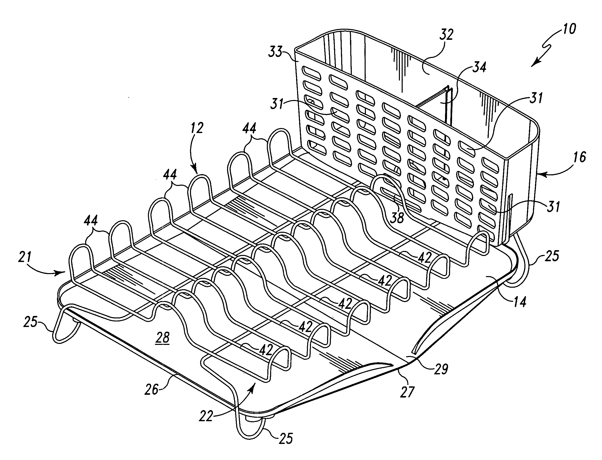
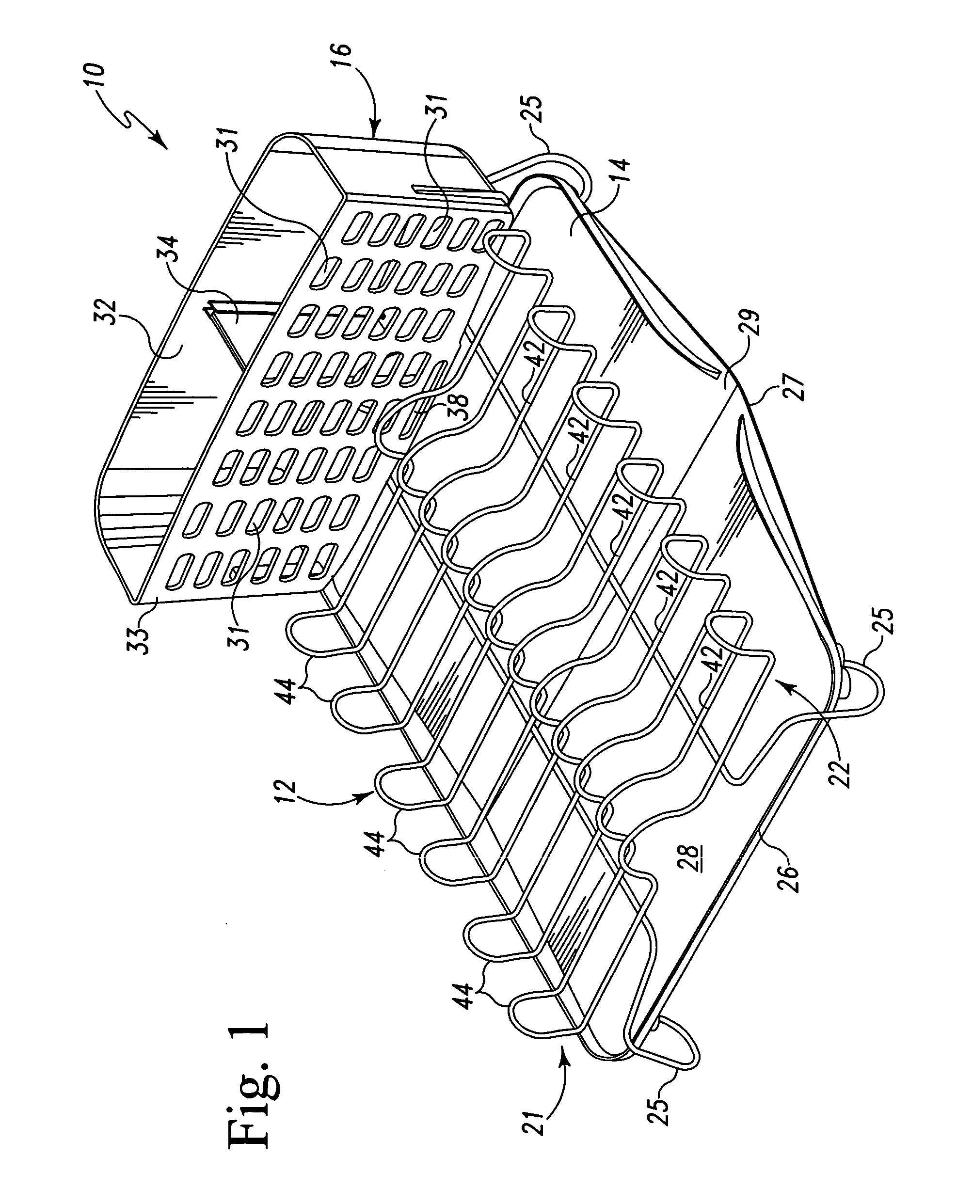
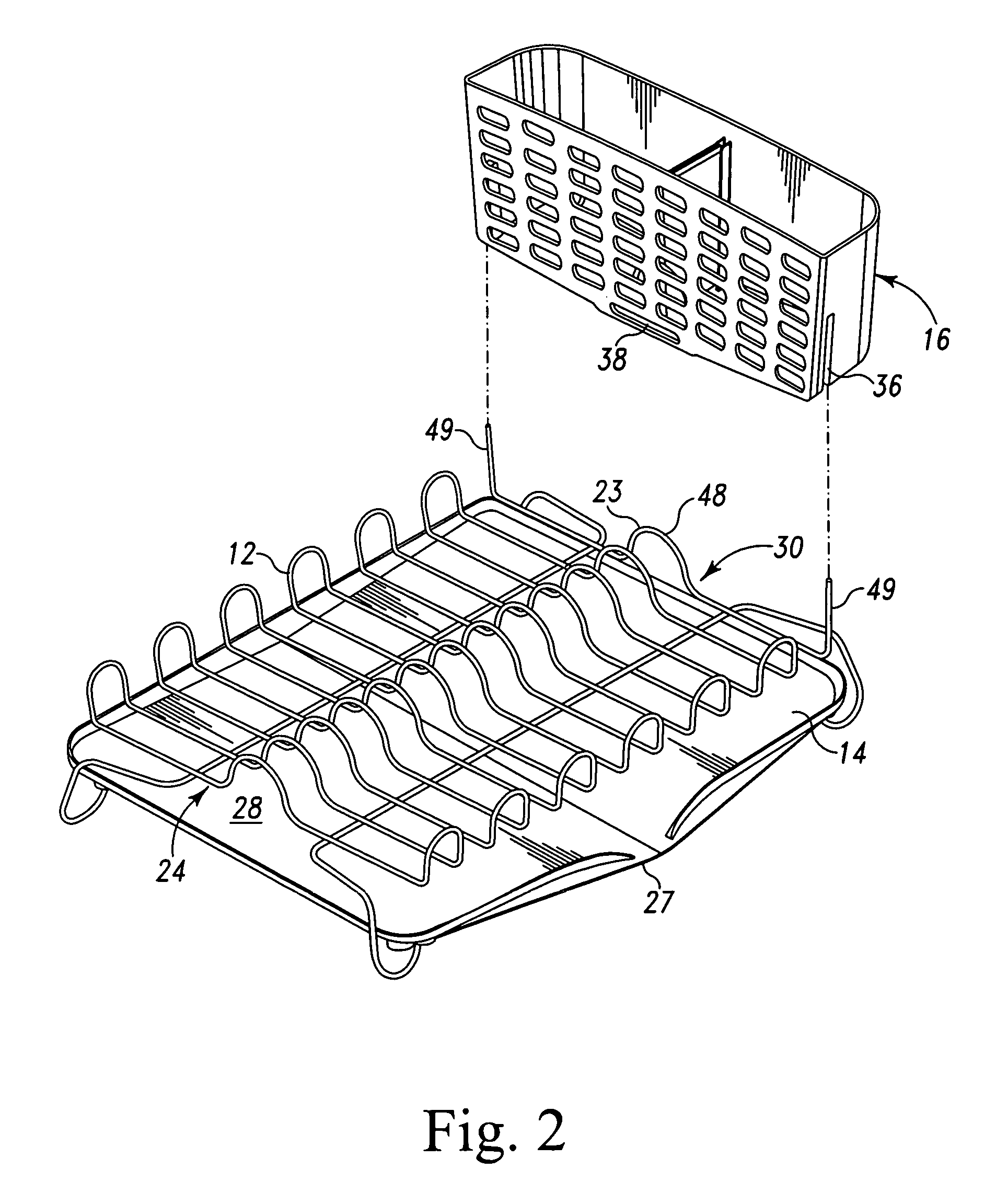
[0023]Referring to the appended FIGS. 1-10, the following discussion references component 10 as a drying storage rack or merely as rack 10. In the illustrated embodiments the drying storage rack 10 includes a rack component 12, a drain mat 14, and a detachable basin 16.

[0024]The rack component 12, with particular reference to FIGS. 1 and 2, is constructed substantially of a coated wire frame in the present embodiment. The rack component 12 includes an upper surface 20 having a plurality of distinct zones, two side surfaces 21, 22, created by the upward vertical extension of the horizontal surface wires 42 of ...


PUM


Abstract

A storage rack for retaining items to be dried, which can be used in conjunction with a drain basin, such as a sink, or as a stand alone system is disclosed. The rack includes a rack component having a first and second ends, first and second sides, and a plurality of foot members, a drain mat supported by the foot members, and a detachable basin attached to a side or end of the rack component. The drain mat includes two sets of positioning members of two distinct lengths on a lower surface. By engaging longer positioning members on one side of the mat and shorter positioning members on the opposite side of the mat, the mat is held in a sloped configuration. The slope may be either toward the integral spout, thereby draining water from the mat, or opposite the integral spout, thereby retaining a substantial amount of water on the mat. The latter configuration permitting the storage rack to be used as a stand alone system.

Description

TECHNICAL FIELD[0001]The present invention relates to a rack for storing utensils, such as, for example, plates, bowls, pots, pans, flatware, and the like, for drying. More specifically, the present invention relates to a drying rack for use with or without a drain sink.BACKGROUND OF THE INVENTION[0002]As long as there has been kitchens, there has been dirty dishes. As long as there has been dirty dishes, there has been a need to wash and dry such dishes. There are basically two widely accepted methods for accomplishing this least favorite task of most every person—i.e., washing and drying by hand or by use of an automatic dishwasher. For those still employing the former method, hand drying has typically been considered inferior to air drying. However, air drying requires the wet dishes to be exposed to the air for some time to allow water to be drained or evaporated.[0003]Further, a drainage source, such as, for example, a sink or a small plastic tub is not always readily available...

Claims


Application Information

Patent Timeline
Patent Type & Authority Applications(United States)
IPC IPC(8): A47G19/08
CPCA47L19/04
Inventor SULLIVAN, ANNGREGORY, PAUL
Owner HELEN OF TROY LIMITED
Why Eureka
Eureka Blog
Learn More