Electromagnetic fuel injection valve

a fuel injection valve and electromagnet technology, applied in the direction of fuel injection apparatus, fuel feed system, spraying apparatus, etc., can solve the problems of deteriorating reproducibility, movement of the movable valve, and inability to achieve the performance under a concentric state, etc., to achieve stably injecting fuel, reduce the gap, and the effect of hard to be inclined

Inactive Publication Date: 2007-06-28
NIKKI CO LTD
View PDF3 Cites 13 Cited by
  • Summary
  • Abstract
  • Description
  • Claims
  • Application Information

AI Technical Summary

Benefits of technology

[0012] The present invention is made by taking the conditions mentioned above into consideration, and an object of the present invention is to provide an inexpensive electromagnetic fuel injection valve which is operated extremely normally without an adjusting screw and a return spring being inclined even if the adjusting screw and a core made of a normal material are used, is excellent in a durability, can always obtain a stable injection amount, and can reduce an influence by a fuel, an atmospheric temperature and the like.
[0014] In accordance with the present invention, since the connection lever is slidably interposed between the adjusting screw in the axial hole of the core and the return spring, a shaft portion of the adjusting screw becomes short and is hard to be inclined. Further, even if the connection lever is inclined due to some reasons, the connection lever is only in contact with the adjusting screw and is not constrained, so that the connection lever is not affected by the incline of the adjusting screw. In addition, since it is possible to reduce the gap between the connection lever and the axial hole of the core, it is possible to press the return spring in a stable state, and the return spring is normally operated without being inclined, it is possible to stably inject the fuel.
[0015] Further, in the present invention, in the case that the leading end of the shaft portion of the adjusting screw is formed in a semispherical shape, a contact area between the adjusting screw and the connection lever is reduced. Accordingly, a freedom about the joint between the adjusting screw and the connection lever is increased, a constraint relation between both the elements is reduced, and the influence by the incline of the adjusting screw can be reduced.
[0016] Further, in the present invention, in the case that the connection lever and the yoke are respectively formed by materials having different linear expansion coefficients from each other, it is possible to solve an increase of fuel temperature and a change of a coil resistance generated by an increase of the atmospheric temperature or the like, by adjusting a load of the return spring.
[0017] As mentioned above, in accordance with the present invention, it is possible to provide an inexpensive electromagnetic fuel injection valve which uses the adjusting screw and the core made of the normal material similar to the conventional electromagnetic fuel injection valve, can always inject the fuel in a stable state without increasing a working precision and particularly complicating an assembling step, and is excellent in a durability. Further, it is possible to achieve a fixed amount of fuel injection even under a high-temperature atmosphere.

Problems solved by technology

Accordingly, not only a performance under a concentric state can not be achieved, but also a reproducibility is deteriorated.
On the other hand, there has been employed a means for pressure inserting the adjusting means without using any screw, in place of the adjusting screw 5 (not shown), however, the foreign matter such as a chip tends to be generated at a time of production, and there is a risk that a motion of the movable valve 23 is affected, and a fuel leak is generated due to an engagement of a seat portion.

Method used


Image

  • Electromagnetic fuel injection valve
  • Electromagnetic fuel injection valve
  • Electromagnetic fuel injection valve

Examples


Embodiment Construction

[0029] Next, a description will be given in detail of preferred embodiments in accordance with the present invention with reference to the accompanying drawings.

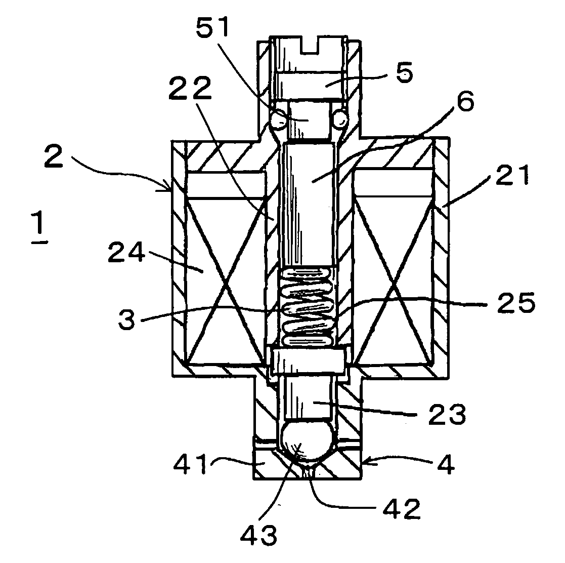
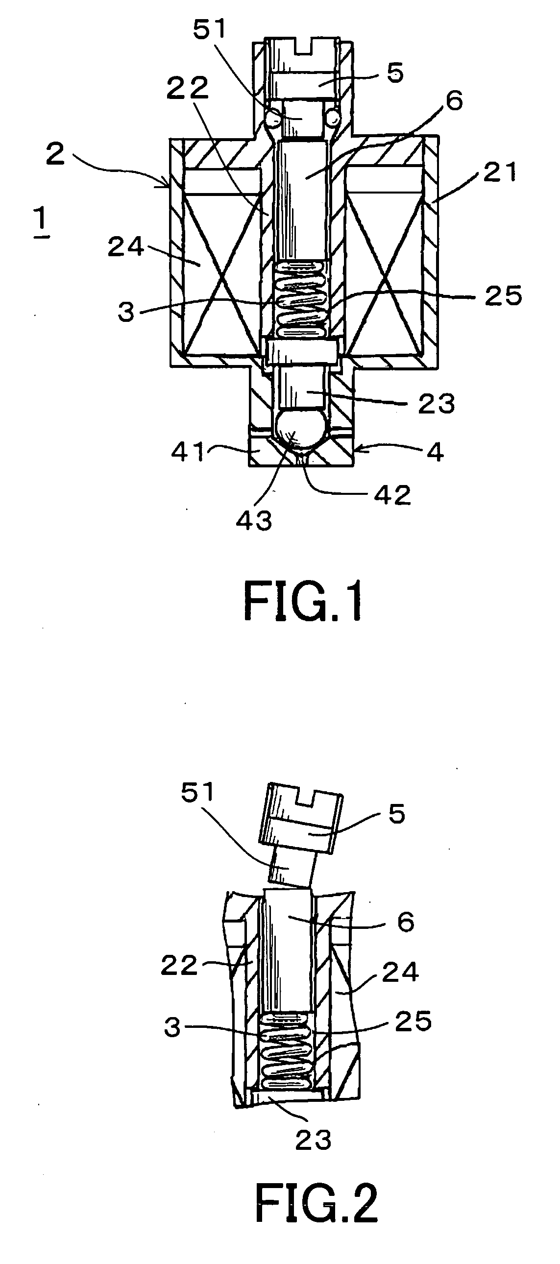
[0030]FIG. 1 shows a preferable embodiment in accordance with the present invention. An electromagnetic fuel injection valve 1 in accordance with the present invention is the same as the conventional one shown in FIG. 8 in a basic structure, and is structured such that an electromagnetic valve 2 corresponding to a drive source is constituted by a yoke 21, a core 22 and a movable valve 23, and an injection valve 4 formed by a ball valve 43 pressed to an injection port 42 of an injection nozzle 41 by a return spring 3 arranged in a base end of the movable valve 23 is arranged in a leading end of the movable valve 23, the movable valve 23 is sucked against a pressing force (a valve closing force) of the return spring 3 on the basis of a magnetic force generated in a coil 24 wound around the core 22, whereby the injection valve...


PUM


Abstract

The invention provides an electromagnetic fuel injection valve which is operated extremely normally, is excellent in a durability, can always obtain a stable injection amount, and can reduce an influence by a fuel, an atmospheric temperature and the like. In an electromagnetic fuel injection valve (1) in which an electromagnetic valve (2) corresponding to a drive source is constituted by a yoke (21), a core (22) and a movable valve (23), an injection nozzle (41) interiorly provided with a ball valve (43) and having an injection port (42) for injecting a fuel is arranged in a leading end of the movable valve (23) so as to form an injection valve (4), and a return spring (3) bonded to the movable valve (23) and an adjusting screw (5) pressure supporting the return spring (3) are arranged in an axial hole (25) of the core (22) by being fitted and inserted to the axial hole (25) of the core (22) from an opening in a base end side, a connection lever (6) is slidably interposed between the adjusting screw (5) in the axial hole (25) of the core (22) and the return spring (3).

Description

BACKGROUND OF THE INVENTION [0001] 1. Field of the Invention [0002] The present invention relates to a fuel injection valve supplying a fuel to an engine which can obtain an output by burning a gasoline or the other fuels, and more particularly to an electromagnetic fuel injection valve structured such as to adjust a fuel injection amount of the engine by an electromagnetic valve and a return spring. [0003] 2. Description of the Related Art [0004]FIG. 8 is a vertical cross sectional view of a conventional electromagnetic fuel injection valve 1, for example, disclosed in Japanese Unexamined Patent Publication No. 55-40391, Japanese Unexamined Patent Publication No. 6-336961, Japanese Unexamined Patent Publication No. 7-151034 and the like. The electromagnetic fuel injection valve 1 is structured such that an electromagnetic valve 2 corresponding to a drive source is constituted by a yoke 21, a core 22 and a movable valve 23, and an injection valve 4 formed by a ball valve 43 pressed ...

Claims


Application Information

Patent Timeline
Patent Type & Authority Applications(United States)
IPC IPC(8): F02M51/00B05B1/30
CPCF02M51/0667F02M51/0692F02M61/205
Inventor MURAKAMI, TSUTOMUOHNISHI, KOUSUKEKONAGAI, GENSAKU
Owner NIKKI CO LTD
Why Eureka
Try Eureka