Supporting device for automotive portable electronic instruments

a technology for supporting devices and electronic instruments, applied in the direction of machine supports, building scaffolds, other domestic objects, etc., can solve the problems of driver distraction from driving, accidents, and inability to properly provide the above functions

Inactive Publication Date: 2007-06-28
LIN ROOKY
View PDF16 Cites 34 Cited by
  • Summary
  • Abstract
  • Description
  • Claims
  • Application Information

AI Technical Summary

Benefits of technology

[0013]Recently, with the development in computer and wireless Internet, a salesman or someone who needs to do his business outside the office can upgrade his car to become a small mobile office. In view of this, present invention is to provide a supporting device for automotive

Problems solved by technology

However, if someone needs to drive the car and uses the computer on the front passenger's seat at the same time, such action will cause the driver to distract from driving, and even an accident may be happened.
In the case that the car is not running, since the front passenger's seat is not a real desk or bracket, it cannot properly provide the above functions.
As a result, the user has to submit himself to the construction of the front passenger's seat and thus will feels uncomfortable.
In general, a running car produces great vibration.
Such a structure may be able to support a lighter device (e.g. cellar phone), but cannot provide a sufficient force to support a heavier device (e.g. laptop).
Therefore, when the car is running, the electronic device being supported by the above structure may be liable to shake or even fall off.
In general, the greater the rigidity of the joint structure is, the worse the ability for bending is.
However, when the user intends to adjust

Method used


Image

  • Supporting device for automotive portable electronic instruments
  • Supporting device for automotive portable electronic instruments
  • Supporting device for automotive portable electronic instruments

Examples


Embodiment Construction

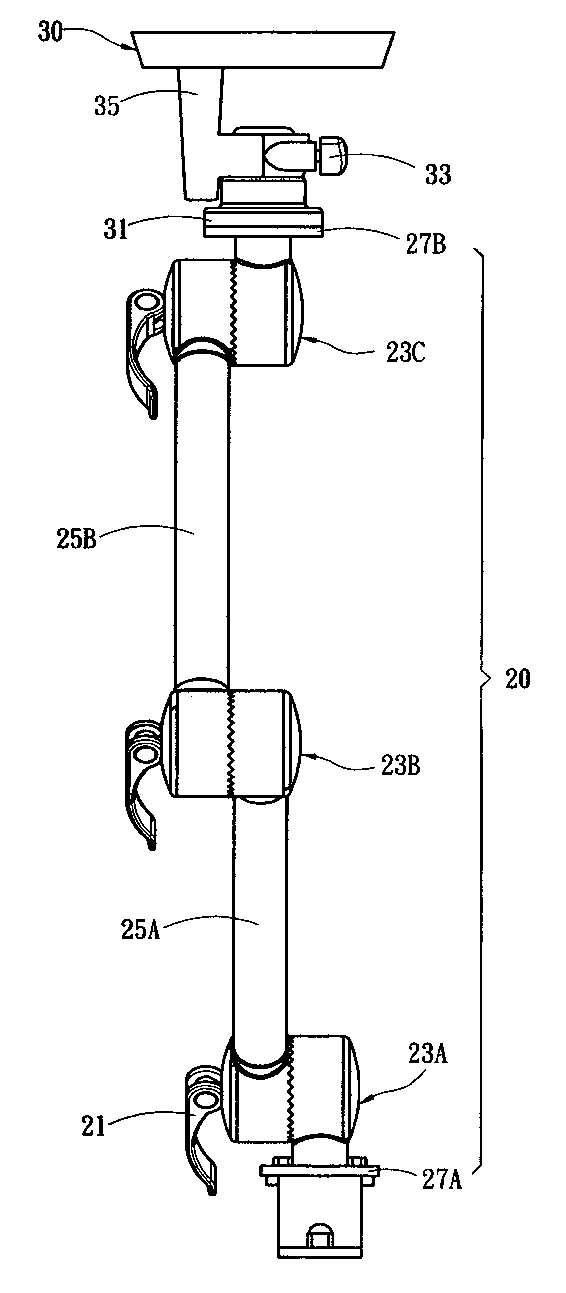
[0019]FIG. 4 is a perspective view of the present invention. The present invention comprises a bendable elongated rod 20, and both ends thereof are connected to a bracket 30 and a base 10, respectively. The elongated rod 20 comprises three connector 23 and two tubular connecting rods 25 each arranged between adjacent connectors. As seen from a first connecting rod 25A, both ends are connected to a first connector 23A and a second connector 23B. Then, the second connector 23B is connected to a second connecting rod 25B. The other end of the second connecting rod 25B is connected to a third connector 23C. Since those connectors 23 are constructed to vary their relative angles, those connectors 23 and connecting rods 25 are totally connected to form the bendable elongated rod 20.

[0020]FIG. 5 is an exploded perspective view of the present invention. With reference to FIGS. 4 and 5, the distal end of the elongated rod is provided with a disc-like first assembly 27A formed of a tube centr...


PUM


Abstract

A supporting device for automotive portable electronic instruments is formed of a bendable elongated rod with both ends connected to a bracket and a base, respectively. The elongated rod includes plural wheel-like connectors rotatable in vertical and axial directions and plural tubular connecting rods arranged between adjacent connectors. Each connector has two wheel-like casings facing and engaging with each other, and the edge of the connecting surface of each casing is correspondingly provided with waved serrations, such that two wheels can be rotatably engaged with each other and positioned by the serrations. Further, a disc-like knob is connected between the elongated rod and the bracket. The bracket is able to rotate around the knob as the center of rotation. A fixing screw is used to force and fix the position of the bracket. Finally, the base is a bent plate provided with plural screw holes, and both ends of the base are connected to the car body and the elongated rod, respectively, thereby to fix the supporting device in the car.

Description

BACKGROUND OF THE INVENTION[0001]1. Field of the Invention[0002]The present invention relates to a supporting device, and in particular to a supporting device capable of for being fixed on the bottom of an in-car space and the angle thereof is adjustable.[0003]2. Description of Prior Art[0004]With the development of semiconductor and battery technologies, electronic products are tending to be more and more compact. Further, with the increasing popularization of automotive video, navigation and GPS, portable products such as notebook, pocket PC, color monitor, DVD player or mobile phone are also more and more popular. Thus, many users (e.g. salesman) can even do their business in a car when they leave the office and on the way to visit a client, causing the car to become a mobile office. As a result, there is a tendency to use other electronic products when driving. Normally, when using in a car, the electronic product is temporarily put on the front passenger's seat beside the drive...

Claims


Application Information

Patent Timeline
IPC IPC(8): E04G3/00
CPCB60R11/02B60R11/0252B60R2011/0029B60R2011/0087B60R2011/0089F16C11/10F16M11/04F16M11/08F16M11/12F16M11/14F16M11/2021F16M13/00F16M13/02F16M2200/021
Inventor LIN, ROOKY
Owner LIN ROOKY
Why Eureka
Try Eureka