Closed observational device for electron microscope

a closed observation and microscope technology, applied in the field of electron microscopes, can solve the problems of damage to the microscope, inauthentic observation, disabling successful imaging of the electron beam or the experiment of electron diffraction, etc., and achieve the effect of easier and clearer observation

Inactive Publication Date: 2007-06-28
CONTREL TECH CO LTD
View PDF8 Cites 30 Cited by
  • Summary
  • Abstract
  • Description
  • Claims
  • Application Information

AI Technical Summary

Benefits of technology

[0010]The secondary objective of the present invention is to provide a closed observational device for an electron microscope; none of any liquid exhausts outward or volatilizes to generate a great amount of gas while the liquid is injected into the closed observational device, therefore enabling easier and clearer observation.
[0011]The foregoing objectives of the present invention are attained by the closed observational device formed of a housing. The housing includes a liquid chamber

Problems solved by technology

As known in prior art, while a conventional electron microscope is operated to observe an object, the object has to be a nonvolatile solid for further microscopic observation because of the limitation of the vacuum environment of the specimen chamber inside the electron microscope.
If the object is volatile, such as liquid, gas, or other fluid, the object will generate a great amount of gas upon after being put into the vacuum specimen chamber, and thus, not only the electron beam of the electron microscope will fail to penetrate the object for successful imaging or experiment of electron diffraction, but also high-vacuum area, like electron beam gun, will lower its vacuum level or cause contamination therein, further damaging the microscope.
However, such design has the following drawbacks.
However, such e

Method used


Image

  • Closed observational device for electron microscope
  • Closed observational device for electron microscope
  • Closed observational device for electron microscope

Examples


second embodiment

[0034]In the second embodiment, the gas apertures 26 are mounted with the films 261, such that the vapor or the gas inside the gas chamber 25 does not exhaust through the gas apertures 26 out of the housing 21 to destruct the vacuum environment inside the electron microscope 90, thus attaining the potency of observing the live cell or other specimen 99.

[0035]Referring to FIG. 8, a closed observational device 30 for the electron microscope according to a third preferred embodiment of the present invention is formed of a housing 31.

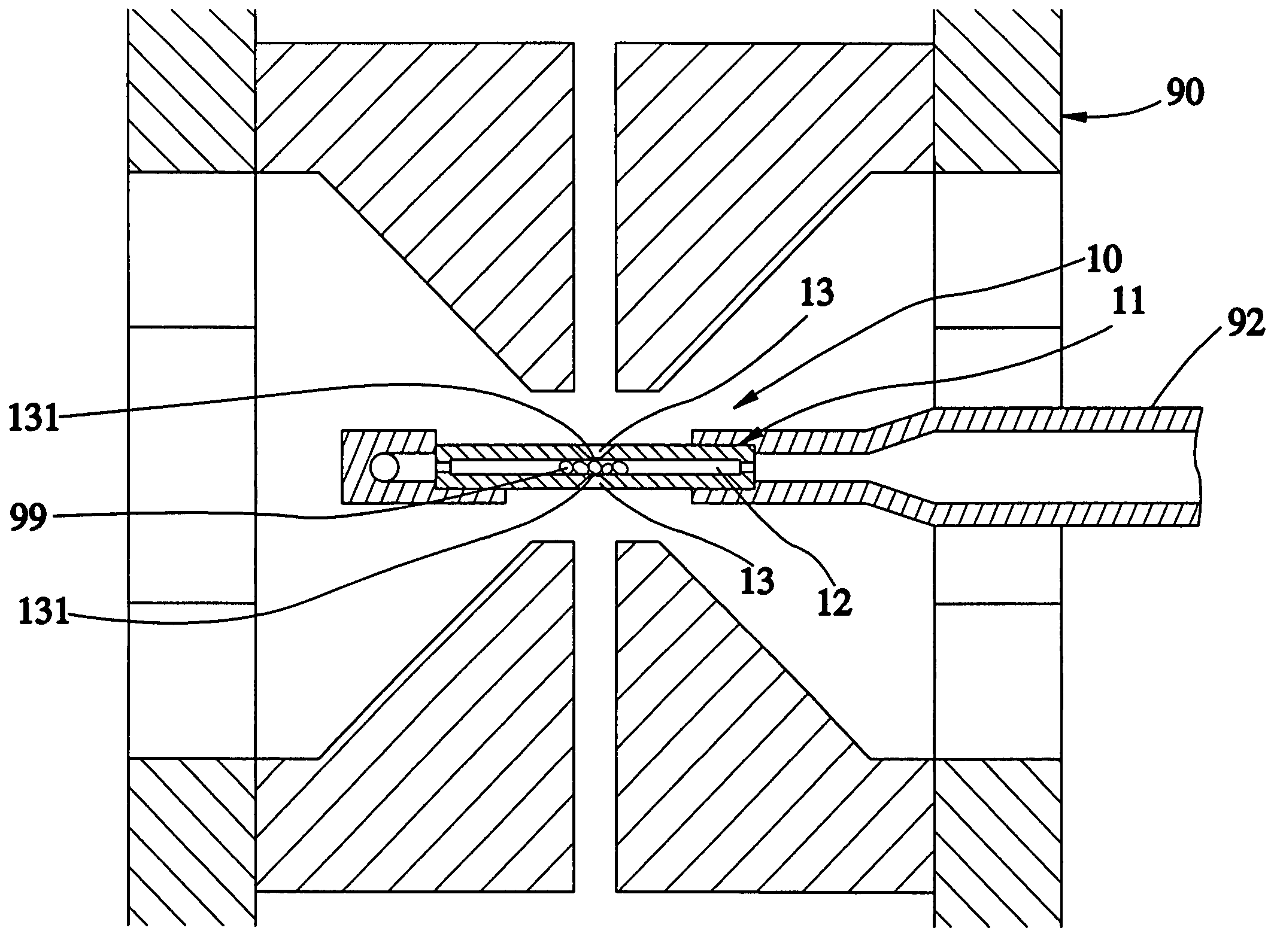
[0036]The housing 31 includes at least two spacers 34, which are defined as four spacers 34 in this embodiment, for partitioning an inner space thereof into a liquid chamber 32, two gas chambers 35 formed above and below the liquid chamber 32 respectively and encapsulating the view holes 33, and two buffer chambers 37 formed above and below the two gas chambers 35 respectively. At least one view hole 33 is formed at each of a top side of and a bottom side o...

third embodiment

[0039]In the aforementioned third embodiment, the upper and lower buffer chambers 37 are for example only but not to limit the scope of the claim the present invention. Multiple-layered upper and lower buffer chambers can also enable the same observation to be one of equivalents of the present invention and should be covered by the scope of the claim of the present invention.

[0040]Referring to FIG. 9, the primary part of the present invention can alternatively be combined with the specimen holder 92 having a box 94′ by that the gas chambers 35′ and the buffer chambers 37′ incorporate with the receiving chamber 32′ formed in the box 94 of the specimen holder 92. The operation is the same as that of the third embodiment and thus more descriptions are not necessary.

[0041]Further, FIG. 10 shows the enabling status that the two buffer chambers 37″ incorporate with the receiving chamber 32″ formed in the box 94″ of the specimen holder 92 and the gas chambers 35″. The box 94″ is formed in ...

first embodiment

[0044]In addition, in the aforementioned embodiments, the liquid chamber can receive the live-cell specimen 99 which can be fixed to the internal surfaces or sidewalls of the liquid chamber or alternatively fixed to the film mounted on one of the view holes as mentioned in the

[0045]The advantages of the prevent invention are as follows:[0046]1. Providing an environment for the microscopic observation of the specimen or the live cell[0047]The present invention enables the general specimen or the live cell to be put into the liquid chamber for the observation under the electron microscope, thus overcoming the problems of the prior art which fails to observe the live cell.[0048]2. No damage to the electron microscope[0049]While the liquid is injected into the liquid chamber, the film can prevent the liquid inside the liquid chamber from escape or outward volatilization. Thus, the present invention enables the microscopic observation to be more easy and clear without damage to the elect...


PUM


Abstract

A closed observational device for an electron microscope is formed of a housing. The housing includes a liquid chamber formed therein, at least one view hole formed at each of a top side thereof and a bottom side thereof and communicating with the liquid chamber and coaxially aligned with the other, and a film mounted to and sealing each of the view holes. Accordingly, a general specimen or a live cell can be placed into the liquid chamber for microscopic observation under the electron microscope. Besides, the present invention can enclose the liquid inside the housing to prevent the liquid from exhausting outward or volatilization.

Description

BACKGROUND OF THE INVENTION[0001]1. Field of the Invention[0002]The present invention relates generally to electron microscopes, and more particularly, to a closed observational device for an electron microscope.[0003]2. Description of the Related Art[0004]As known in prior art, while a conventional electron microscope is operated to observe an object, the object has to be a nonvolatile solid for further microscopic observation because of the limitation of the vacuum environment of the specimen chamber inside the electron microscope. If the object is volatile, such as liquid, gas, or other fluid, the object will generate a great amount of gas upon after being put into the vacuum specimen chamber, and thus, not only the electron beam of the electron microscope will fail to penetrate the object for successful imaging or experiment of electron diffraction, but also high-vacuum area, like electron beam gun, will lower its vacuum level or cause contamination therein, further damaging the...

Claims


Application Information

Patent Timeline
IPC IPC(8): G21K5/10
CPCH01J37/20H01J2237/188H01J2237/2004H01J2237/262
Inventor CHAO, CHIH-YUHSIEH, WEN-JIUNN
Owner CONTREL TECH CO LTD
Why Eureka
Try Eureka