Removable valve seat member for diaphragm valve

a diaphragm valve and valve seat technology, which is applied in the direction of diaphragm valves, engine diaphragms, operating means/releasing devices of valves, etc., can solve the problems of valve seat creep, care must be taken, and the valve cannot function properly, so as to prevent the creep of the valve seat, facilitate the effect of less obstruction, and improve understanding

Active Publication Date: 2007-06-28
CRANE INSTR & SAMPLING INC
View PDF39 Cites 12 Cited by
  • Summary
  • Abstract
  • Description
  • Claims
  • Application Information

AI Technical Summary

Benefits of technology

[0009] An advantage of the present invention is that it allows for replacement of a valve seat for a diaphragm valve without replacing the valve.
[0010] Another advantage of the present invention is that it prevents creep of a valve seat for a diaphragm valve.
[0011] A further advantage of the present invention is that it applies a constant compressive force to retain a valve seat in position in the valve body.
[0012] Other features and advantages of the present invention will be apparent from the following more detailed description of the preferred embodiment, taken in conjunction with the accompanying drawings which illustrate, by way of example, the principles of the invention. Corresponding reference characters indicate corresponding components throughout the several views of the drawings. Skilled artisans will appreciate that elements in the figures are illustrated for simplicity and clarity and have not necessarily been drawn to scale. For example, the dimensions of some of the elements in the figures may be exaggerated relative to other elements to help to improve understanding of various embodiments of the present invention. Also, common but well-understood elements that are useful or necessary in a commercially feasible embodiment are typically not depicted in order to facilitate a less obstructed view of these various embodiments of the present invention.

Problems solved by technology

After being subjected to operational use, especially involving caustic or abrasive fluids and / or particulates or condensates, valve components, notably the valve seats, become worn or damaged so that the valve can no longer function properly.
In addition to the cost of the replacement valve, care must be taken to ensure the system connections to the replacement valve do not leak.
However, for reasons including the difference in thermal coefficients of expansion / contraction between the non-metallic valve seat member and the metallic valve body, the valve seat member is susceptible to working loose from the valve body.
Moreover, the process of press-fitting the tightly fitting ring inside the valve base will necessarily deform the surface of the valve base contacting the diaphragm, which will compromise the quality of the seal between the valve base and the diaphragm.
Finally, due to a portion of the valve base flowing into the groove in the opening securing the valve base within the valve body as it is deformed, it is unlikely that the valve base can be removed without damaging the valve body, which would necessitate replacement of the entire valve.

Method used


Image

  • Removable valve seat member for diaphragm valve
  • Removable valve seat member for diaphragm valve
  • Removable valve seat member for diaphragm valve

Examples


Embodiment Construction

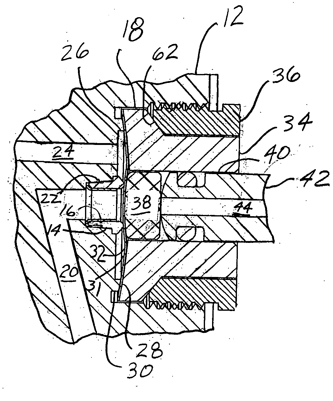
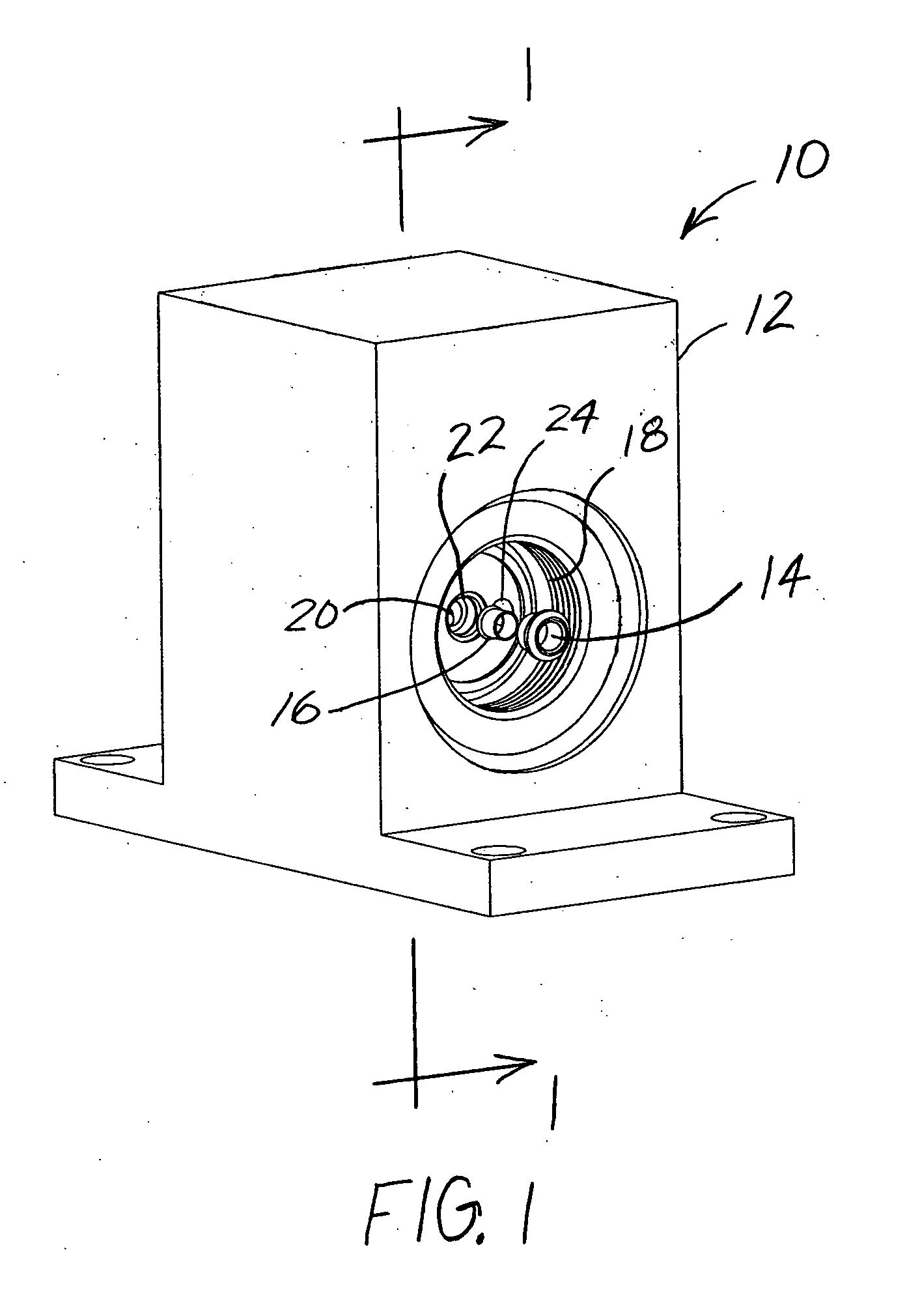
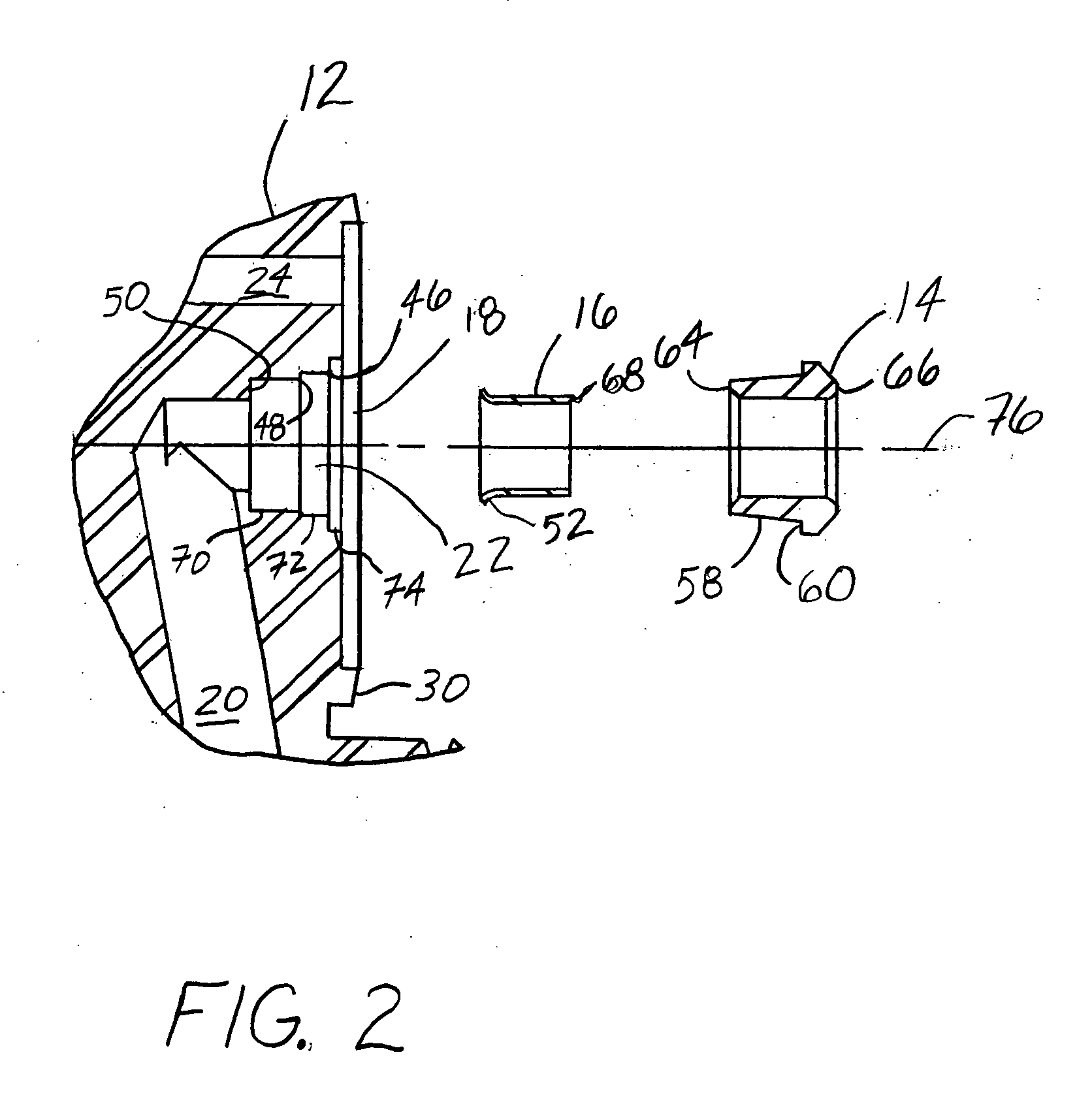
[0019] One embodiment of a valve 10 of the present invention is depicted in FIG. 1. Preferably, referring to FIGS. 1-5, valve 10 includes a valve body 12 having a valve cavity 18 further opening into separate channels 20, 24 for directing a fluid through the valve body 12. A counterbored penetration or bore 22 receives a sleeve 16 and a seat member 14 that are preassembled prior to insertion into the bore 22. A diaphragm 28 is installed over the seat member 14, and a collet 34 is then installed in the valve cavity 18 over the diaphragm 28. Collectively, a lower portion 26 of the valve cavity 18, including an annular ridge 30 extending outwardly from the valve cavity 18 and the diaphragm 28 define an enclosed region 32 for permitting the selective flow of fluid between the channels 20, 24. To secure the diaphragm 28 between the annular ridge 30 of the valve body 12 and the collet 34, a nut 36 having a tapered shoulder 62 is threadedly engaged to abut a corresponding tapered surface o...


PUM


Abstract

An apparatus and method for a diaphragm valve includes a valve body having a chamber in fluid communication with a first channel and a second channel. A diaphragm is disposed in the chamber, and a tapered seat member is at least partially disposed in the first channel. A sleeve is compressively disposed in the seat member between the seat member and the first channel to maintain a fluid tight seal between the seat member and the first channel. A valve member is movable to controllably urge the diaphragm into and out of engagement with the seat member to control flow of fluid between the first the first and second channel.

Description

FIELD OF THE INVENTION [0001] The present invention is directed to a valve construction, and more particularly, the present invention is directed to a valve seat construction for diaphragm valves. BACKGROUND OF THE INVENTION [0002] Valves are widely used to provide precision flow and / or pressure control of fluids. Diaphragm valves are preferred in many applications due to the valve member being directed into and out of contact with a diaphragm, which likewise directs a valve seat into and out of engagement with the diaphragm to effect the desired fluid flow / pressure control. Other attributes diaphragm valves have are low internal volume, high sealing integrity, compact size and fast actuation / operation. [0003] After being subjected to operational use, especially involving caustic or abrasive fluids and / or particulates or condensates, valve components, notably the valve seats, become worn or damaged so that the valve can no longer function properly. One solution is to replace the ent...

Claims


Application Information

Patent Timeline
Patent Type & Authority Applications(United States)
IPC IPC(8): F16K1/00
CPCF16K7/14F16K1/425F16K7/16F16K1/42
Inventor LOWERY, PATRICK A.
Owner CRANE INSTR & SAMPLING INC
Why Eureka
Try Eureka