Rotating machine
a technology of rotating machines and pole shoes, which is applied in the direction of dynamo-electric machines, electrical equipment, magnetic circuit shapes/forms/construction, etc., can solve the problems of often occurring and achieve the effect of preventing displacement and peeling of pole shoes
- Summary
- Abstract
- Description
- Claims
- Application Information
AI Technical Summary
Benefits of technology
Problems solved by technology
Method used
Image

Examples
example 1
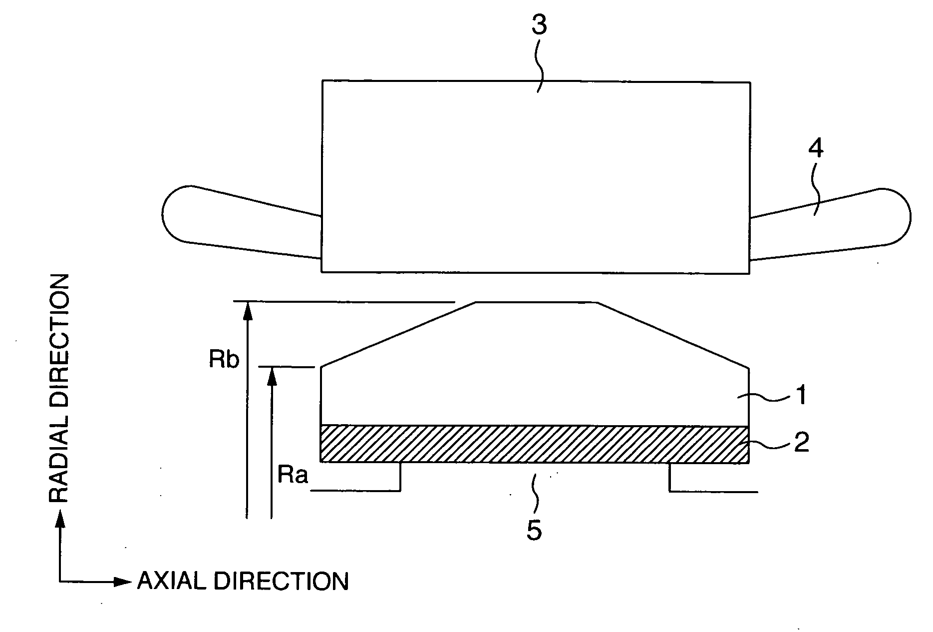
[0032] Now, in Example 1 of the present invention, as shown in FIG. 1, magnetic poles are configured by disposing permanent magnets 2 between pole shoes 1 and pedestals 5 formed in a rotor. The pole shoes 1 and the permanent magnets 2 are fixed by fastening by non-magnetic magnetic bolts or winding of a biding band. The permanent magnets 2 is magnetized so as to show radial anisotropy in the radial direction. Incidentally, the pole shoes are configured by a ferromagnetic material such as iron, and efficiently transfers a magnetic flux emitted from the permanent magnet to stator windings. Further, though it is conceivable to provide the permanent magnet on the surface of the rotor, since the rotor rotates at a high speed, it is conceivable that the permanent magnet is deteriorated and flown away. Hence, the permanent magnet is held down by the pole shoes 1 having a hardness from the outside of the permanent magnets. Further, to hold down the permanent magnet from the outside by the p...
example 2
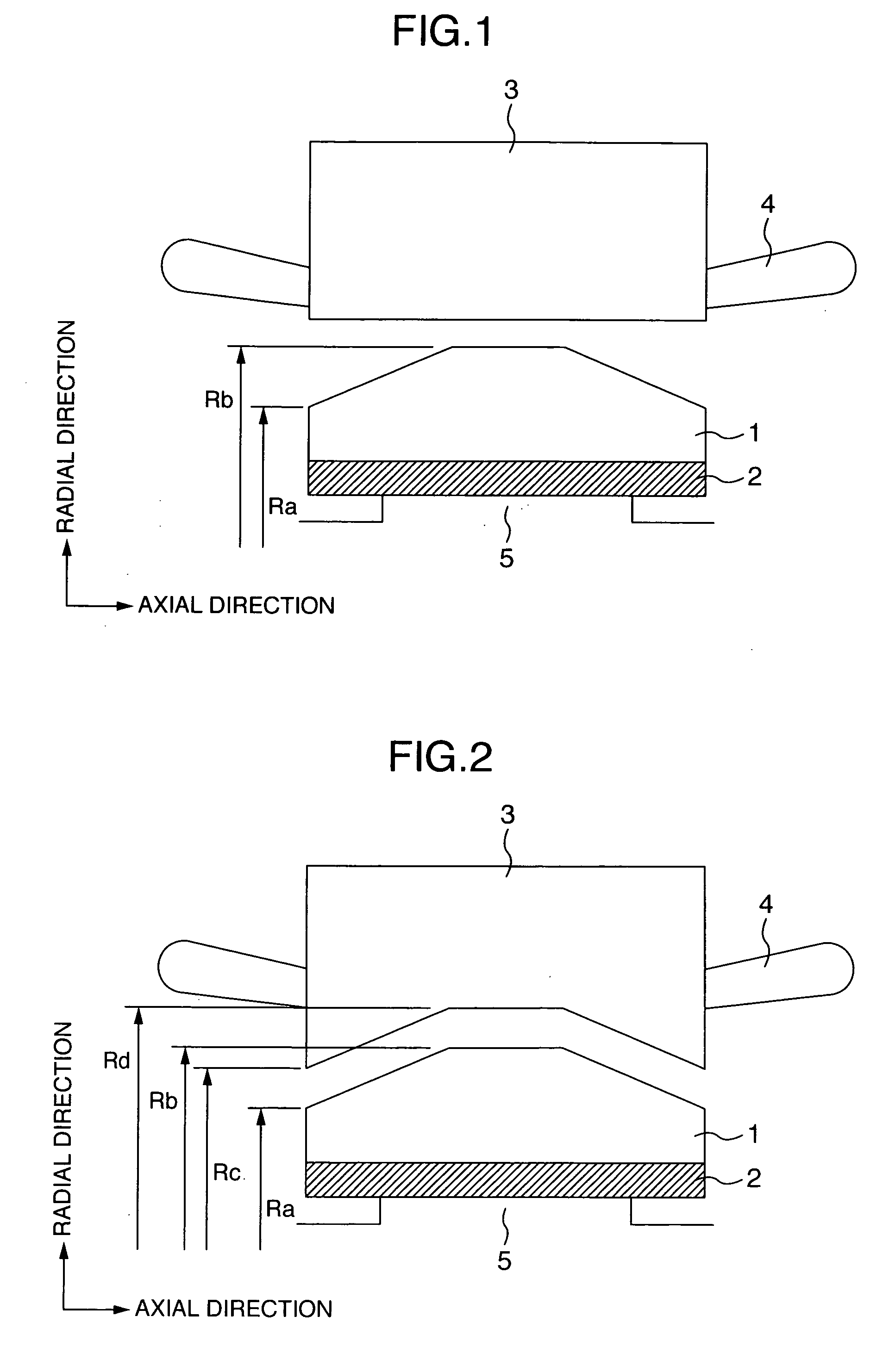
[0035] Incidentally, in Example 1, when the outer diameter of both axial ends of the rotor is made smaller, a gap with the inner diameter of the stator becomes larger, and therefore, there arises a problem that a flux leakage is increased and an output is reduced.
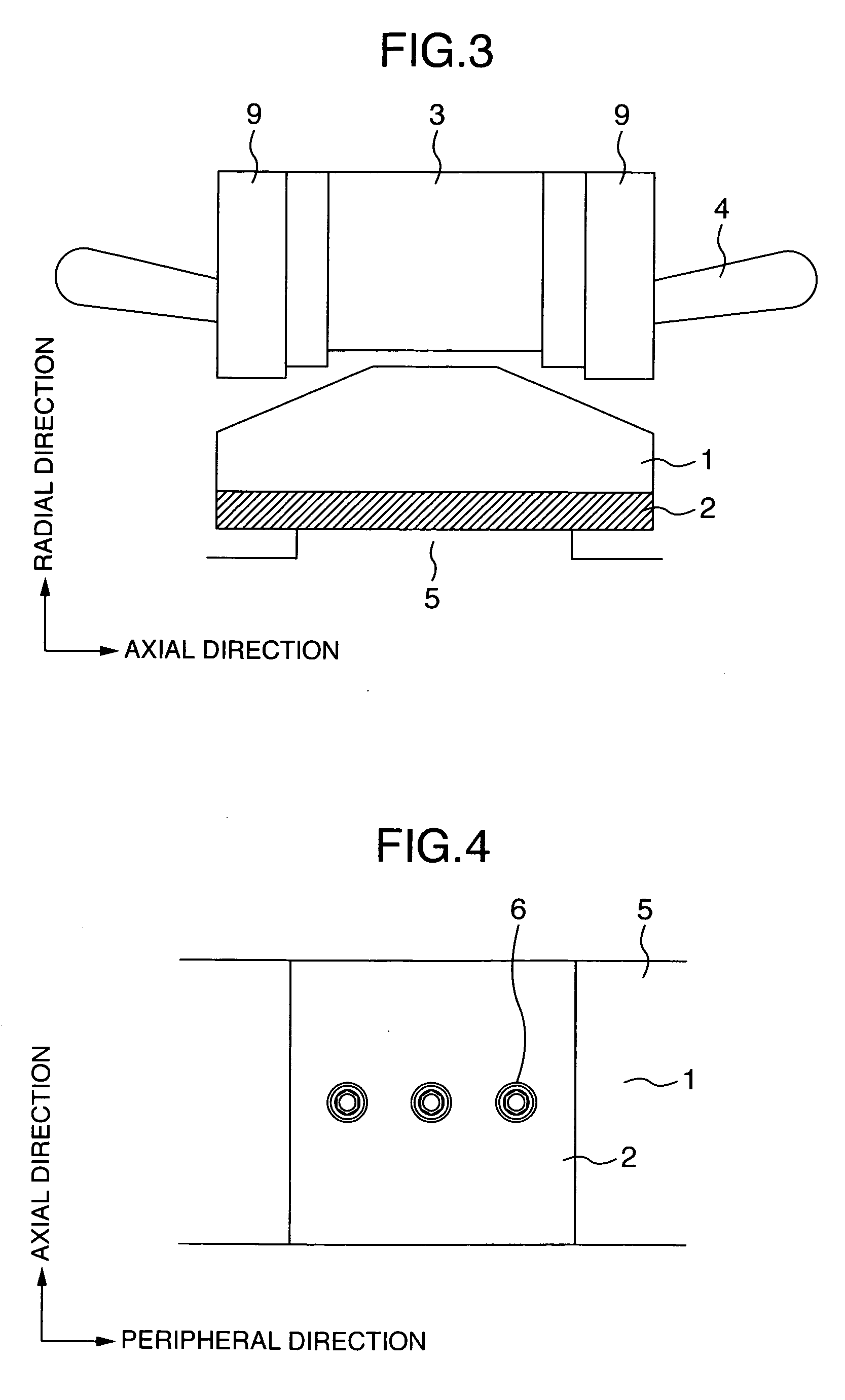
[0036] Hence, in Example 2 of the present invention, as shown in FIGS. 2 and 3, an inner diameter size Rc in an axial end portion of a stator iron core 3 is made smaller than an inner diameter size Rd in the axial center portion. As a result, a flux leakage in both axial ends is prevented, and a reduction of output is prevented.
[0037] In FIG. 19, the solid line shows the output voltage as a function of ratio Wpt / Wps of the upper surface of diameter Wpt and the lower surface diameter Wps of the pole shoe in case of the stator core 3 with same axial inner diameter at the axial end portion as at the axial center portion.
[0038] On the other hand, the broken line shows the output voltage as a function of ratio Wpt / Wps in case...
example 3
[0042] Example 3 of the present invention will be shown in FIGS. 4 to 6. The present example shows one example of a rotor of a rotating machine according to the present invention, and FIG. 4 is a view of a magnetic pole seen from a radial direction, FIG. 5 is a view seen from a peripheral direction, and FIG. 6 is a view seen from an axial direction, respectively. A pole shoe 1 and a permanent magnet 2 having a rectangular section are fastened to a pedestal 5 by a magnetic bolt 6. The pole shoe 1 has a smaller outer diameter in the axial center portion than in the axial end portion, thereby preventing displacement and peeling in axial both ends of the pole shoe due to a centrifugal force at the rotating time.
[0043] Here, when an attempt is made to hold the pole shoe and the permanent magnet by a plurality of bolts, a load is applied to a specific bolt, and therefore, the bolt or a bolt hole has possibilities of being broken. On the other hand, when the pole shoe having a square sect...
PUM
 Abstract
Description
Claims
Application Information
 - R&D
- Intellectual Property
- Life Sciences
- Materials
- Tech Scout
- Unparalleled Data Quality
- Higher Quality Content
- 60% Fewer Hallucinations
Browse by: Latest US Patents, China's latest patents, Technical Efficacy Thesaurus, Application Domain, Technology Topic, Popular Technical Reports.
© 2025 PatSnap. All rights reserved.Legal|Privacy policy|Modern Slavery Act Transparency Statement|Sitemap|About US| Contact US: help@patsnap.com