

Detector circuit to be used for measuring current
- Summary
- Abstract
- Description
- Claims
- Application Information
AI Technical Summary
Benefits of technology
Problems solved by technology
Method used
Image

Examples
Embodiment Construction
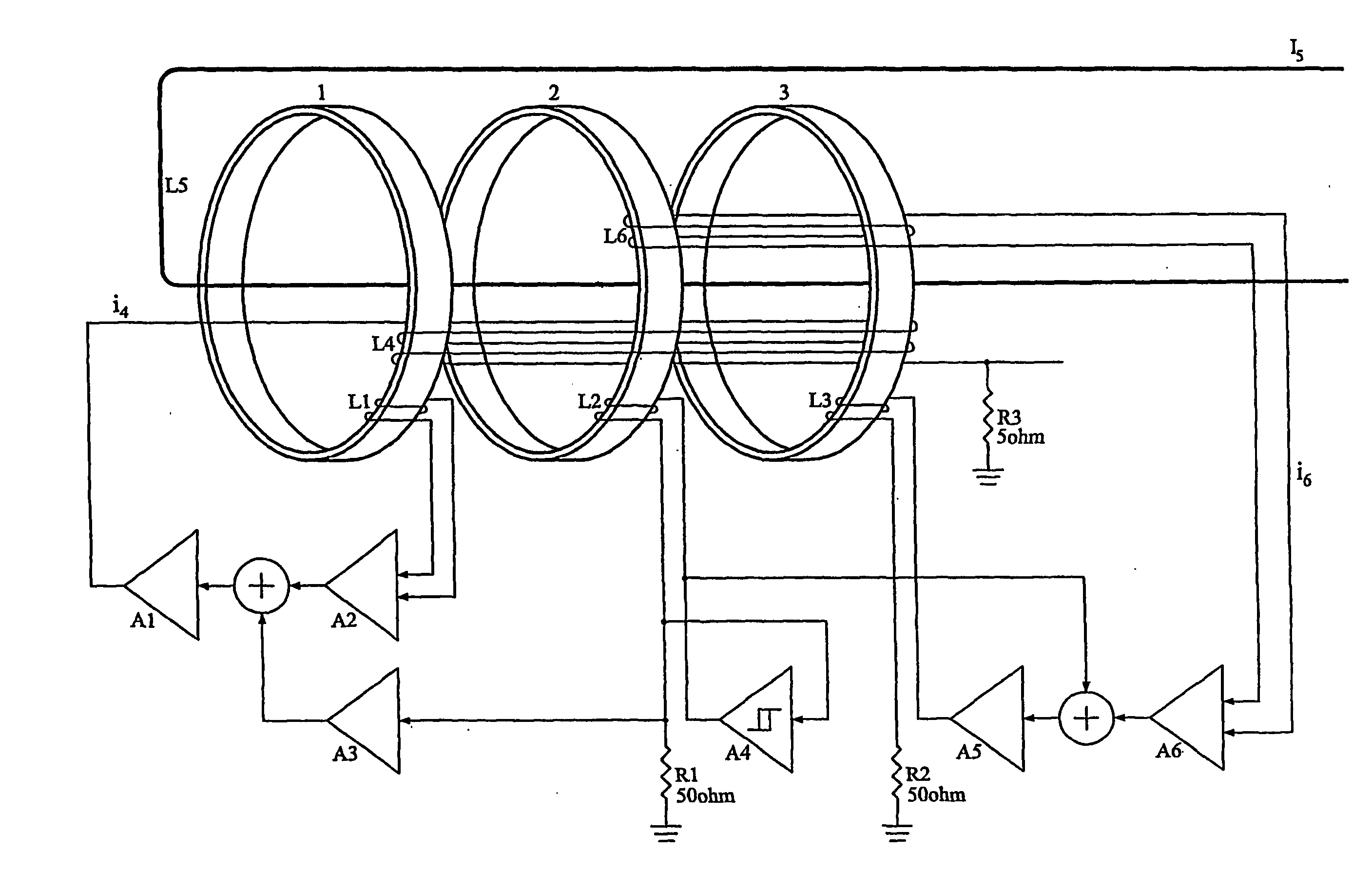
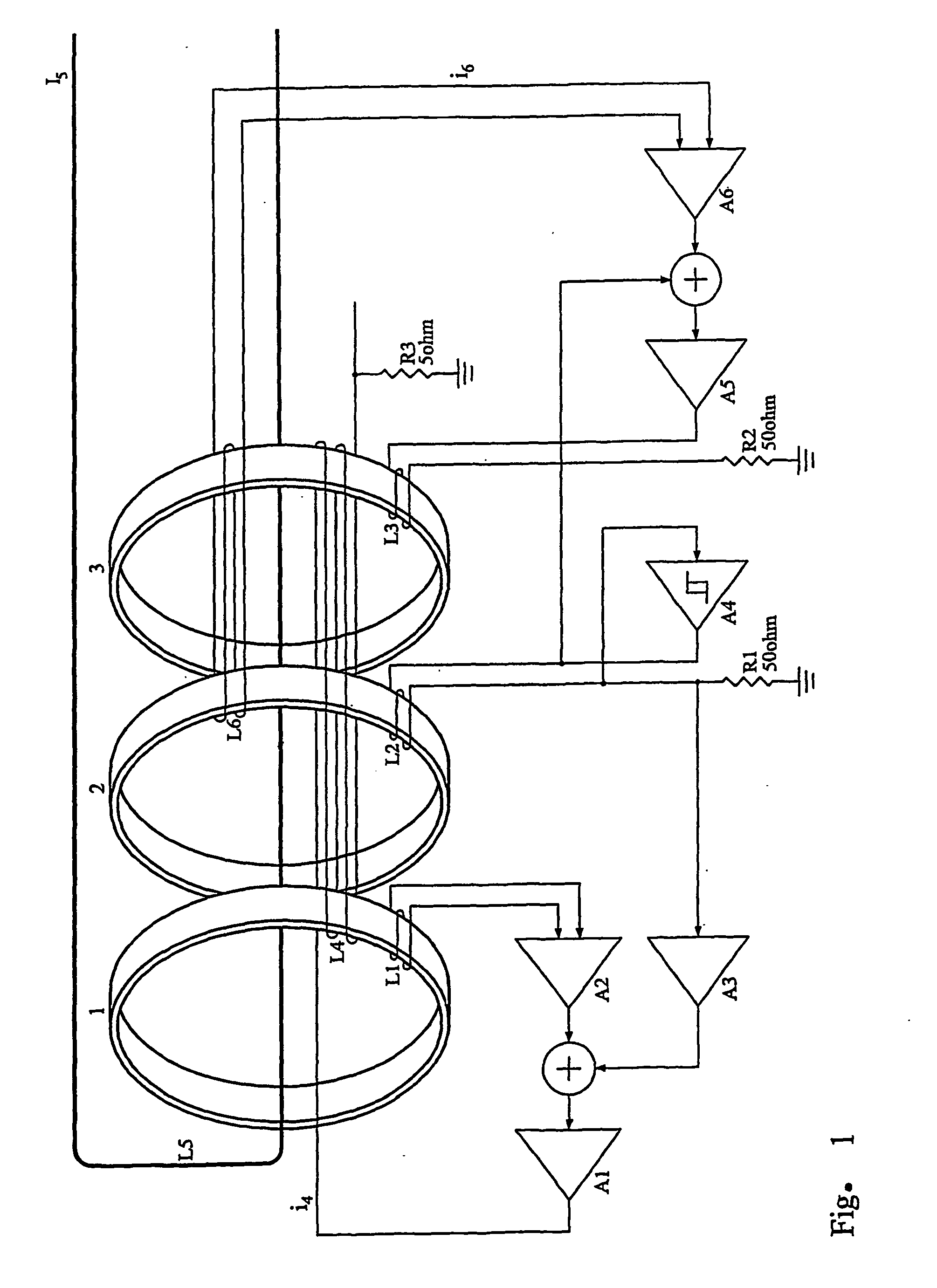
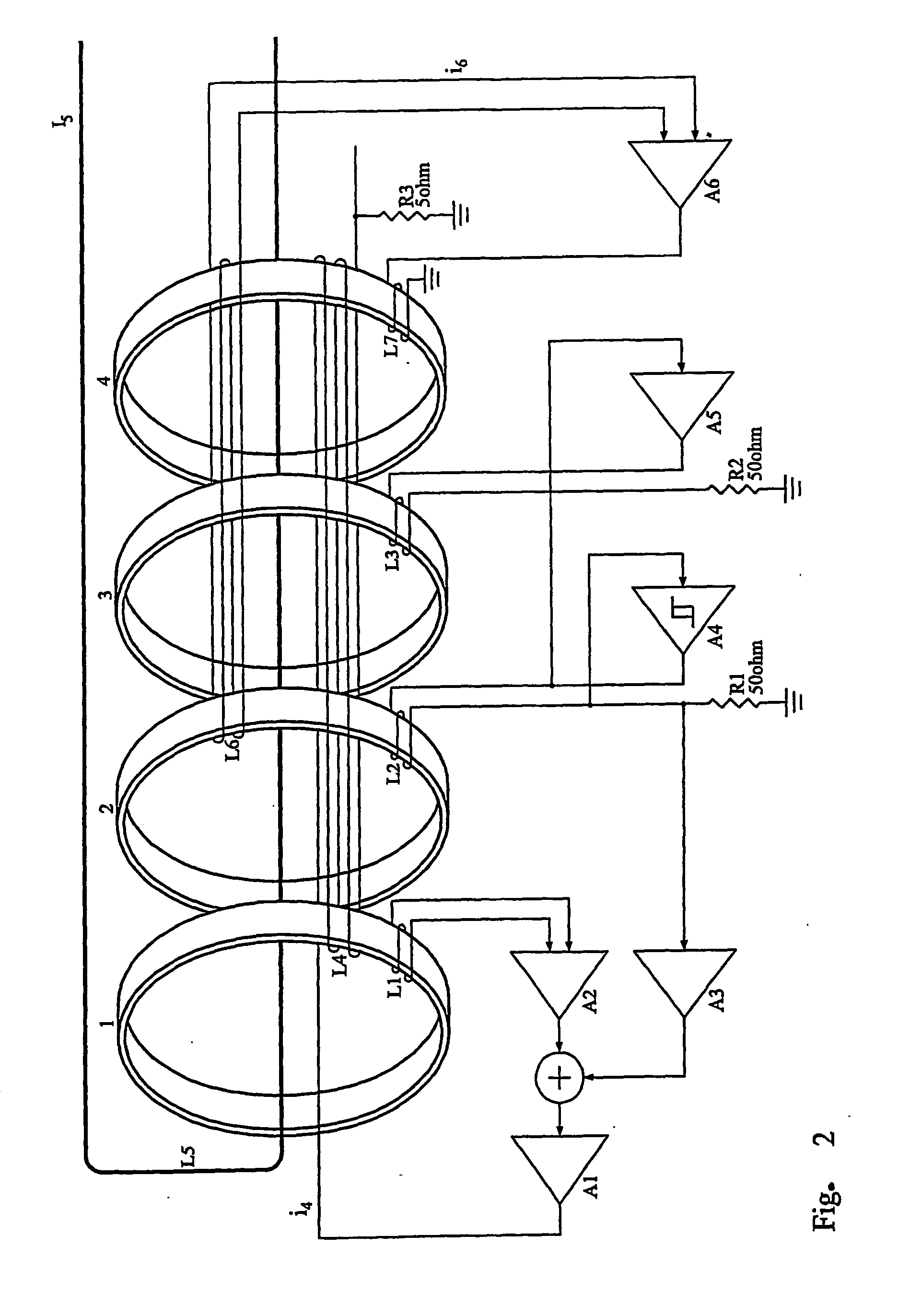
[0006] The object of the invention is therefore to show how it is possible in a simple manner to carry out a correction while the measuring of the current is carried out This object is according to the invention obtained by the means for compensating for possible differences between the ring core transformers being formed by a common winding surrounding the two ring cores, said common winding detecting a possible error signal used in a negative feedback loop which automatically seeks to establish an equilibrium.
[0007] An active compensation may according to the invention be carried out by one core being used as a detector, viz. a master, while the second core is used as a slave. Then a winding surrounding both cores catches a difference signal / error signal which is amplified and added to the control signal for the slave core with the result that the signal coupled to the compensating circuit is reduced approximately 50 times.
[0008] Moreover, a negative feedback loop may according ...
PUM
 Abstract
Description
Claims
Application Information