Interface antenna

a technology of interface antenna and antenna, which is applied in the direction of instruments, burglar alarm mechanical actuation, electrographic process, etc., can solve the problems of unfavorable communication between readers and designers, and achieve the effect of increasing the distance over which the tag can communica

Active Publication Date: 2007-06-28
XEROX CORP
View PDF6 Cites 45 Cited by
  • Summary
  • Abstract
  • Description
  • Claims
  • Application Information

AI Technical Summary

Benefits of technology

[0009] According to one aspect, there is provided an interface antenna for increasing a distance over which a tag can communicate with a reader. When the interface antenna is positioned between a tag antenna associated with the tag and a reader antenna associated with the reader, the interface antenna receives an electromagnetic carrier signal transmitted by the reader antenna and causes an increase in intensity of the electromagnetic carrier signal at the location of the tag antenna, thereby increasing the distance over which the tag can communicate with the reader.
[0010] In another aspect, there is provided a package for an object where the object has a tag associated therewith for wirelessly communicating data with a reader external to the package. The package includes an interface antenna for increasing a distance over which the tag can communicate with the reader. When the interface antenna is positioned between a tag antenna associated with the tag and a reader antenna associated with the reader, the interface antenna receives an electromagnetic carrier signal transmitted by the reader antenna and causes an increase in intensity of the electromagnetic carrier signal at the location of the tag antenna, thereby increasing the distance over which the tag can communicate with the reader.
[0011] In yet another aspect, there is provided a packaging label having an interface antenna attached thereto for increasing a distance over which a tag can communicate with a reader. When the interface antenna is positioned between a tag antenna associated with the tag and a reader antenna associated with the reader, the interface antenna receives an electromagnetic carrier signal transmitted by the reader antenna and causes an increase in intensity of the electromagnetic carrier signal at the location of the tag antenna, thereby increasing the distance over which the tag can communicate with the reader.
[0012] In yet another aspect, there is provided a method for increasing a distance over which a tag can communicate with a reader. The method comprises: positioning an interface antenna between a tag antenna associated with the tag and a reader antenna associated with the reader, wherein the interface antenna receives an electromagnetic carrier signal transmitted by the reader antenna and causes an increase in intensity of the electromagnetic carrier signal at the location of the tag antenna, thereby increasing the distance over which the tag can communicate with the reader.

Problems solved by technology

Problematically, it is unlikely that the designed communication range can be maintained at every desired point of access (e.g., during production, packaging, shipping, and installation).
The distance over which the tag and the reader can communicate can be increased by increasing the size of the antenna on the tag; however, smaller tags are more desirable because of cost and space considerations.

Method used


Image

  • Interface antenna
  • Interface antenna
  • Interface antenna

Examples


Embodiment Construction

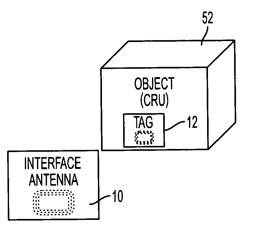
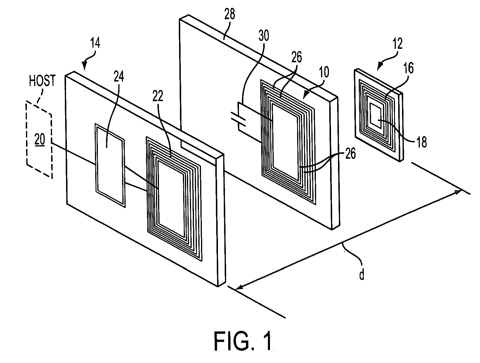
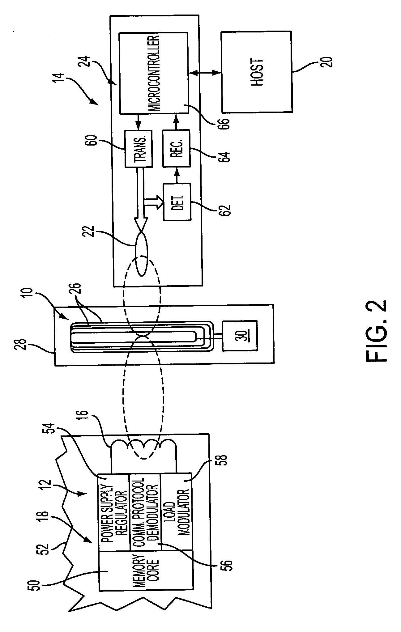
[0025]FIG. 1 depicts an interface antenna 10 for increasing a distance over which a tag (also known as a transponder) 12 can communicate with a reader (also known as an interrogator, transceiver, or coupler) 14. The tag 12 is typically attached to an object (not shown), and includes a tag antenna 16 and an integrated circuit (IC) device 18. Stored within the IC device 18 is information related to the object to which the tag 12 is attached. While this information usually includes identification data for the object, it may include other information related to, or used by, the object, as will be described in further detail hereinafter. It is contemplated that the object to which the tag 12 is attached may be any tangible item. In one embodiment, described hereinafter with respect to FIG. 8, the object includes a replaceable module for a machine, also referred to as a CRU (Customer Replaceable Unit), and the tag 12 is configured as a CRUM (Customer Replaceable Unit Monitor).

[0026] The ...


PUM


Abstract

An interface antenna is positioned between a tag antenna associated with a tag and a reader antenna associated with a reader. The interface antenna receives an electromagnetic carrier signal transmitted by the reader antenna and causes an increase in intensity of the electromagnetic carrier signal at the location of the tag antenna, thereby increasing the distance over which the tag can communicate with the reader. Where the tag is attached to a packaged object, the interface antenna may be included in the package to allow wireless data communication between the tag and a reader external to the package. For example, the interface antenna may be attached to a label on the package. At least a portion of the interface antenna may be formed from a conductive ink applied to the label and / or the container. The object may be a module, also known as a customer replaceable unit (CRU), and the tag may be configured as a customer replaceable unit monitor (CRUM).

Description

BACKGROUND [0001] A common trend in machine design, particularly in the office equipment industry, is to organize a machine on a modular basis, wherein certain distinct subsystems of the machine are bundled together into modules which can be readily removed from the machine and replaced with new modules of the same or similar type. A modular design facilitates great flexibility in the business relationship with the customer. By providing subsystems in discrete modules, also known as “customer replaceable units” or CRUs, visits from a service representative can be made very short, since all the representative has to do is remove and replace a defective module. Actual repair of the module may take place remotely at the service provider's premises. Further, some customers may wish to have the ability to buy modules “off the shelf,” such as from an equipment supply store. Indeed, it is possible that a customer may lease the machine and wish to buy a supply of modules as needed. Further,...

Claims


Application Information

Patent Timeline
Patent Type & Authority Applications(United States)
IPC IPC(8): G08B13/14
CPCG06K7/0008G06K7/10178
Inventor PHIPPS, WILLRODRIGUEZ, ALBERTOBELL, SCOTT J.ROMMELMANN, HEIKOHART, STEVEN C.
Owner XEROX CORP
Why Eureka
Try Eureka