Image forming apparatus and method

a technology of image forming and forming apparatus, which is applied in the direction of printing, other printing apparatus, etc., can solve the problems of shape disruption and inability to obtain high-quality images, and achieve the effect of deposition interferen

Inactive Publication Date: 2007-06-28
FUJIFILM CORP
View PDF4 Cites 10 Cited by
  • Summary
  • Abstract
  • Description
  • Claims
  • Application Information

AI Technical Summary

Benefits of technology

[0030] According to the present invention, by achieving droplet ejection conditions which allow deposition interference to be suppressed by introducing the concept of the overlap-permissible diameter d2 of the mist dots, then high-speed, high-quality printing becomes possible, without being subject to the restriction of the dot fixing time.

Problems solved by technology

However, if the mist is ejected to form dots on a recording medium in an overlapping fashion at high speed by using the mist spraying type of recording head, then deposition interference occurs between the formed dots, the dot shapes are disrupted and color mixing may arise between the dots, and therefore a high-quality image cannot be obtained.

Method used


Image

  • Image forming apparatus and method
  • Image forming apparatus and method
  • Image forming apparatus and method

Examples


Embodiment Construction

Structure of Ink Ejection Head

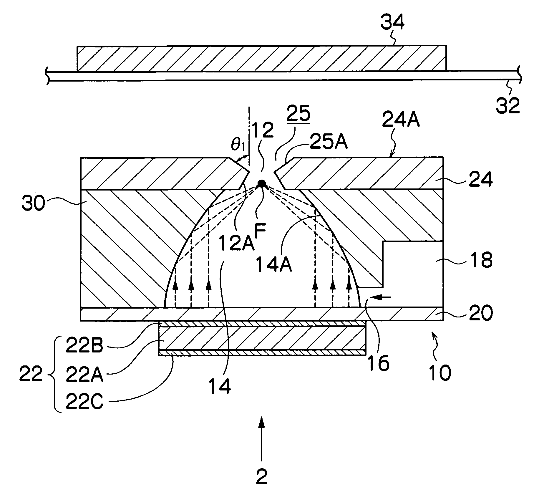
[0051]FIG. 1 is a cross-sectional view showing the basic configuration of a mist spraying device (ink ejection head) in an image forming apparatus according to an embodiment of the present invention. The mist spraying device 10 shown in FIG. 1 includes a nozzle 12 as an ejection port for ink mist, an ink chamber 14, an ink supply port 16, a common flow channel 18 which accommodates ink to be supplied to the ink chamber 14, an insulating resin film 20, and a piezoelectric element 22 serving as a mist generating device. FIG. 1 shows a cross-sectional view of an ink chamber unit corresponding to one nozzle 12 (the liquid droplet ejection element for one channel). When this ink chamber unit is applied to a print head (also referred to as a “recording head”) or another such mist ejecting head, a plurality of channels are arrayed either one-dimensionally (in a row) or two-dimensionally (across a plane).

[0052] The nozzle plate 24 in which the nozzles 12 are...


PUM


Abstract

The image forming apparatus includes: a liquid chamber into which ink is filled; an ejection port through which the ink is ejected from the liquid chamber; a mist generation device which generates a mist from a surface of the ink inside the ejection port by applying vibration energy to the ink in the liquid chamber; an electric field generation device which generates an electric field causing the mist ejected from the ejection port to move to a recording medium; and a setting device which sets at least one of drive conditions of the mist generation device and a recording resolution in such a manner that a relationship Pt≧d2 is satisfied, where d2 is an overlap-permissible diameter which is a minimum distance between centers of two mist dots formed by the mist on the recording medium that allows shapes of the two mist dots to be fixed as a prescribed shape when the two mist dots are deposited on the recording medium substantially simultaneously under substantially same ejection conditions so as to overlap partially with each other, and Pt is a pitch between the centers of the two mist dots defined by the recording resolution.

Description

BACKGROUND OF THE INVENTION [0001] 1. Field of the Invention [0002] The present invention relates to an image forming apparatus and method, and more particularly to an image forming apparatus and method in which a group of ink micro-particles (ink mist) is generated by ultrasonic waves so as to record images by means of the ink mist. [0003] 2. Description of the Related Art [0004] Japanese Patent Application Publication No. 8-104004 discloses an ink mist type of image recording apparatus (ink mist printer) which records images by generating a flow of ink mist (very fine ink particles) by means of ultrasonic vibration, and depositing this ink mist onto a recording medium as a group (cluster). [0005] In Japanese Patent Application Publication No. 8-104004, in order to create ink mist efficiently, a piezoelectric substrate serving as a vibration source has a concave on the side facing the ink ejection port, at least at an electrode installation region. However, if the mist is ejected t...

Claims


Application Information

Patent Timeline
Patent Type & Authority Applications(United States)
IPC IPC(8): B41J2/06
CPCB41J2/06B41J2/145
Inventor KUSUNOKI, NAOKI
Owner FUJIFILM CORP
Why Eureka
Try Eureka