Scattered light range of view measurement apparatus

Active Publication Date: 2007-06-28
SICK AG
View PDF3 Cites 6 Cited by
  • Summary
  • Abstract
  • Description
  • Claims
  • Application Information

AI Technical Summary

Benefits of technology

[0015] An advantage of the present invention is that with the periodically activated transmissions light path via the light deflector, a desired additional transmission measurement can be made. As compared to the scattered light measurement method, this generates a strong light signal for the light receiver, particularly when the range of sight is good. This then enables a functional testing of the scattered light measuring instrument. Since the transmissions light path uses the same light emitter and the same light receiver as is used during normal scattered light measurements, the instrument of the present invention has the significant advantage that possible component alterations or changes of the optoelectronic components have no effect.
[0016] A further advantage of the present invention is that the geometric spaces traversed by the light are the same and do not differ from each other. This has the advantage that obstacles that may be present in the light radiation space and the optical boundary surfaces are the same for both and can therefore be securely recognized. Such optical boundary surfaces are used in scattered light instruments to protect the instrument from dirt and contamination. Nevertheless, dirt and contaminants can deposit on these optical boundary surfaces, which can interfere with the proper functioning of the instrument. Through the activation of the transmissions light path in accordance with the present invention, even such contaminating deposits are recognized, which is not possible with conventional scattered light range measuring instruments. Since the transmissions light path cannot continuously be active, the present invention provides an optical shutter which temporally controls the opening and closing of the transmissions light path. For this, the present invention contemplates, for example, to interrupt the light path by operating the shutter with a rotatable magnet. It is also possible to operate the shutter with a stepping mot

Problems solved by technology

In particular, such a scattered light range of view measurement instrument should generate an unequivocal indication of the degree of contamination at optical boun

Method used


Image

  • Scattered light range of view measurement apparatus
  • Scattered light range of view measurement apparatus
  • Scattered light range of view measurement apparatus

Examples


Embodiment Construction

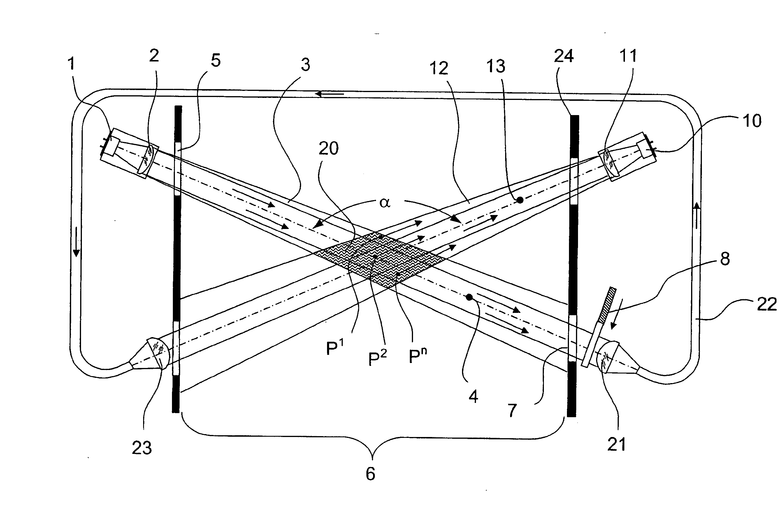
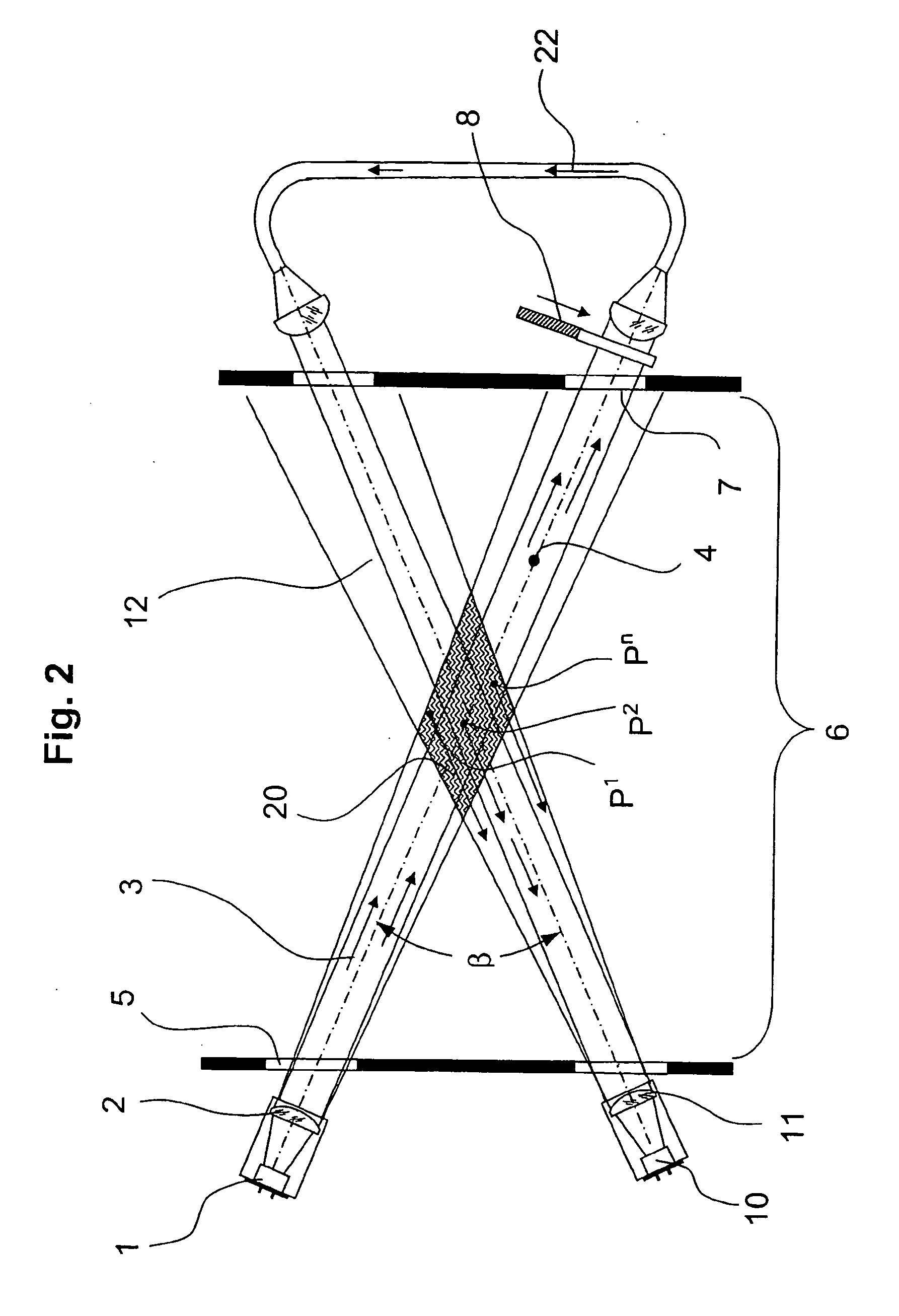
[0024] Referring to FIG. 1, a light emitter 1 that cooperates with an associated emitting optics 2 directs an emitted light beam 3 along an axis 4 of an emitted light beam 3. The light beam 3 traverses an optical end plate 5 from which it enters a testing space 6. The light beam 3 continues and reaches another end plate 7 at the opposite end of testing space 6. After light beam 3 has traversed end plate 7, it reaches an optical shutter 8 which prevents the further expansion of the beam while scattered light is being measured.

[0025] A light receiver 10 which includes a receiving optics 11 is arranged behind a boundary 24 of testing space 6. Light receiver 10 together with receiving optics 11 collect all light that is received from a received light beam 12 and convert the received light quantity into a proportional electrical signal. Received light beam 12 has a received light beam axis 13 which crosses the emitted light beam axis 4 inside testing space 6 at an angle α Since the two ...


PUM


Abstract

A method and apparatus for determining a range of sight which are capable of monitoring and correcting the operability of the instrument. A light emitter directs an emitted light beam to a measurement zone and a light receiver receives a received light beam from the measurement zone. The emitted light beam and the received light beam cross each other in the measurement zone. A deflector deflects at least a portion of the emitted light beam downstream of the measurement zone along a light transmitting path and directs the portion of the emitted light beam into the received light beam at a side of the measurement zone opposite from the light receiver. An optical shutter intermittently closes the light transmitting path in a temporally controlled manner.

Description

RELATED APPLICATIONS [0001] This application claims the priority of European patent application No. 05 027 138.6 filed Dec. 13, 2005, the disclosure of which is incorporated herein by reference. BACKGROUND OF THE INVENTION [0002] The invention concerns a scattered light range of sight measurement instrument which measures the amount of light scattered by a light beam as it traverses a gas sample from which the density of particulates in the gas sample can be established. With this information, the sight range or viewable distance through the sample can be determined. [0003] Stray or scattered light measuring instruments are used for determining the presence of particles (aerosols, dust, etc.) in venting conduits as well as in the atmosphere as a whole. For example, the carbon particle emissions from a chimney can be determined in this way. Scattered light measuring instruments are further used in street traffic, ocean shipping and air transport, and they are used, when appropriate, ...

Claims


Application Information

Patent Timeline
IPC IPC(8): G01N21/00
CPCG01N21/532G01N21/538
Inventor KAUFMANN, JUERGENSCHIFFLER, INGOSMETANA, KLAUS
Owner SICK AG
Why Eureka
Try Eureka