
Image processor and camera system, image processing method, and motion picture displaying method

Active Publication Date: 2007-06-28
MEGACHIPS
View PDF2 Cites 106 Cited by
  • Summary
  • Abstract
  • Description
  • Claims
  • Application Information

AI Technical Summary

Benefits of technology

[0006] It is an object of the present invention to provide a technique capable of correcting an image distortion caused by the rolling shutter type exposure.
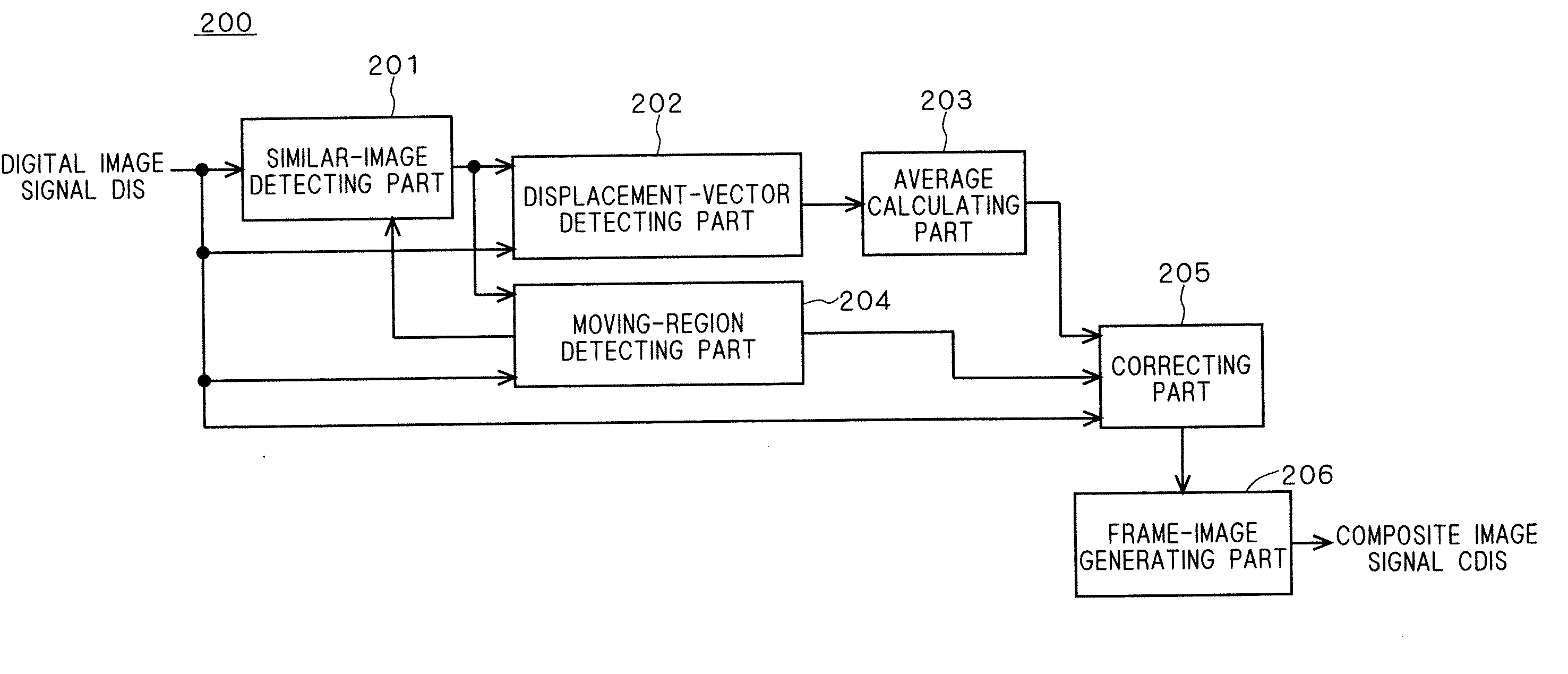
[0008] An average of displacement vectors of similar image regions in the plurality of frame images is calculated, and the similar image region is shifted such that the displacement vector of the similar image region becomes the average. Since hand shake generally occurs at random in a plurality of frame images, the positions of similar image regions similar to one another among the plurality of frame images captured by the rolling shutter type exposure are displaced at random from their original position. Accordingly, an average of displacement vectors of similar image regions with respect to a reference position in the plurality of frame images becomes a value close to the displacement vector of the original position of the similar image regions with respect to the reference position. Therefore, shifting the similar image region such that the displacement vector of the similar image region becomes the average allows the similar image region to be brought close to the original position. This in result can reduce an image distortion caused by the rolling shutter type exposure.
[0010] An average of displacement vectors of a plurality of partial image regions is used for the displacement vector of the similar image region. This reduces an influence upon correction processing caused by an error contained in the displacement vector. Accordingly, an image distortion resulting from the rolling shutter type exposure can be reduced reliably.
[0016] The composite frame image corresponding to a frame image captured during the total exposure time period is generated on the basis of the plurality of frame images captured during short divided exposure time periods, respectively. This can reduce random noise occurring in image signals at image capturing.
[0018] Displaying a motion picture on the basis of the plurality of composite frame images in which image distortions resulting from the rolling shutter type exposure have been corrected. This can provide a user with a motion picture that is easy to see, which is advantageous because the image distortions resulting from the rolling shutter type exposure particularly in a motion picture give great discomfort on the user.

Problems solved by technology

Since the rolling-shutter-type image capturing apparatus provides a different exposure starting time for each pixel or each line of pixels in one frame image as described above, hand shake of a user may cause a distortion of the whole screen of a frame image captured by such image capturing apparatus.

Method used


Image

  • Image processor and camera system, image processing method, and motion picture displaying method
  • Image processor and camera system, image processing method, and motion picture displaying method
  • Image processor and camera system, image processing method, and motion picture displaying method

Examples


first preferred embodiment

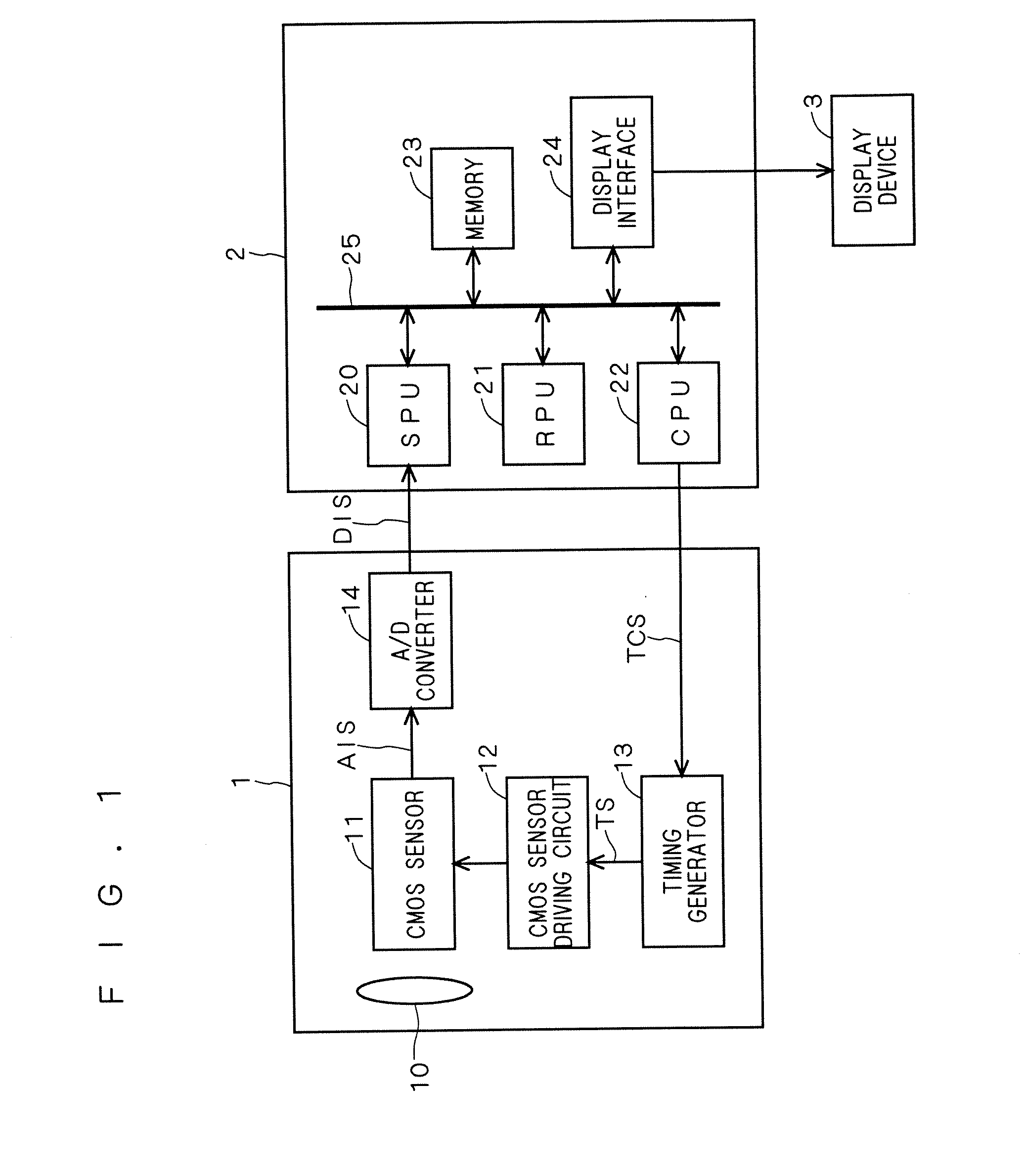
[0045]FIG. 1 is a block diagram showing the configuration of a camera system according to a preferred embodiment of the present invention. The camera system according to the present embodiment is a digital still camera, for example, for capturing images by the rolling shutter type exposure. As shown in FIG. 1, the camera system includes an image capturing apparatus 1 for capturing images, an image processor 2 for carrying out image processing on images captured by the image capturing apparatus 1, and a display device 3 for displaying images processed by the image processor 2. The image capturing apparatus 1, image processor 2 and display device 3 are housed in a single housing, for example.

[0046] The image capturing apparatus 1 has a lens unit 10, a CMOS sensor 11, a CMOS sensor driving circuit 12, a timing generator 13 and an A / D converter 14. The CMOS sensor 11 converts light incident from a subject through the lens unit 10 into an electric signal to capture an image and outputs ...

second preferred embodiment

[0147]FIG. 29 is a block diagram showing the configuration of a camera system according to a second preferred embodiment of the invention. The camera system according to the second preferred embodiment additionally includes a gyro sensor 4 in the camera system according to the first preferred embodiment.

[0148] Hand shake generally occurs at random in a plurality of frame images as described above, but may appear in agreement among a plurality of frame images in some rare cases. FIGS. 30A to 30D show such case. As shown, when hand shake appears in agreement among the frame images FR1 to FR4, these images are the same image except an image of a moving subject. Accordingly, the aforementioned displacement vectors a to d all become zero, in which case an image distortion resulting from the hand shake and rolling shutter type exposure cannot be corrected.

[0149] According to the present embodiment, the gyro sensor 4 detects the amount of shake of the present camera system, and corrects ...


PUM


Abstract

A similar-image detecting part detects similar image regions similar to one another in a plurality of frame images captured by rolling shutter type exposure. A displacement-vector detecting part detects a displacement vector of each of the similar image regions with respect to a reference position in each of the plurality of frame images. An average calculating part calculates an average of displacement vectors in the plurality of frame images. A correcting part shifts a similar image region in one of the plurality of frame images such that the displacement vector of the similar image region becomes the average calculated by the average calculating part.

Description

BACKGROUND OF THE INVENTION [0001] 1. Field of the Invention [0002] The present invention relates to an image processor for carrying out image processing on an image captured by rolling shutter type exposure, and also relates to a camera system equipped with such image processor, and an image processing method of processing such image and a motion picture displaying method. [0003] 2. Description of the Background Art [0004] Conventionally known exposure techniques for capturing images are of global shutter type and rolling shutter type (also called “focal plane shutter type”). A global-shutter-type image capturing apparatus represented by an image capturing apparatus equipped with interline CCD (Charge Coupled Device) sensors provides almost the same exposure time period and exposure starting time for each pixel in one frame image. In contrast, a rolling-shutter-type image capturing apparatus represented by an image capturing apparatus equipped with CMOS sensors provides the same ex...

Claims


Application Information

Patent Timeline
IPC IPC(8): G06K9/32
CPCH04N5/23248H04N5/3532H04N5/357H04N5/2329H04N23/689H04N23/68H04N25/531H04N25/60
Inventor SASAKI, GENNARA, YUSUKE
Owner MEGACHIPS
Learn More